Hi luka,
Voltage amplification was about 17*3.6 so 61
144vpp/61 gives 2.36Vpp at the input...
could you post pics of clipping of output signal ?
Voltage amplification was about 17*3.6 so 61
144vpp/61 gives 2.36Vpp at the input...
could you post pics of clipping of output signal ?
Hi
Could you measure it with scope so I will be 100% sure how much your gain is.
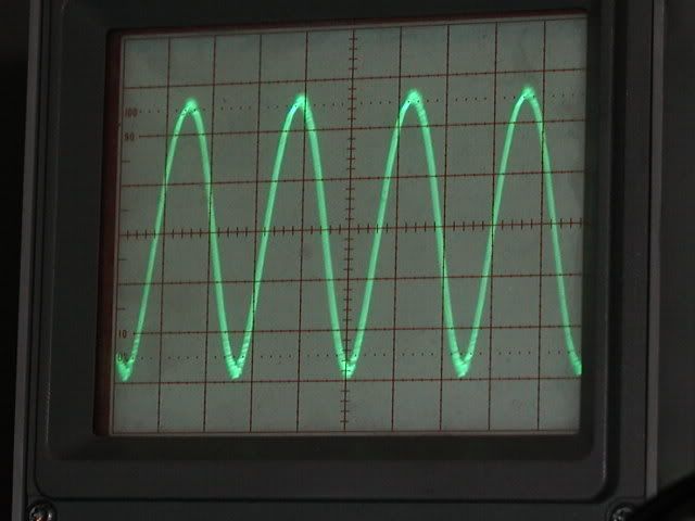
Output (no load) just before clipping. It is that small because generator clips lower period before id does upper one. 10v/div
And this one is with max input that I can give

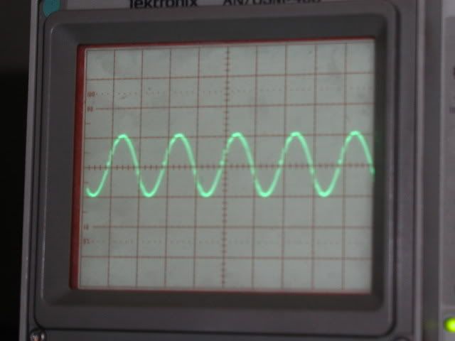
Bender was right, those resistors were inductive, a lot. This is output 250kHz, 0.5v/div
Could you measure it with scope so I will be 100% sure how much your gain is.
Output (no load) just before clipping. It is that small because generator clips lower period before id does upper one. 10v/div
And this one is with max input that I can give
Bender was right, those resistors were inductive, a lot. This is output 250kHz, 0.5v/div
Hi
Much to my surprise spikes on 0.1 resistors are the same size, that I didn't expect.
Now will be time to go to /-50v, and see what will wait for me there. Maybe some destroyed speaker 😀
Much to my surprise spikes on 0.1 resistors are the same size, that I didn't expect.
Now will be time to go to /-50v, and see what will wait for me there. Maybe some destroyed speaker 😀
i don't think so, i hope everything gonna be alright.luka said:
Now will be time to go to /-50v, and see what will wait for me there. Maybe some destroyed speaker 😀
Hi
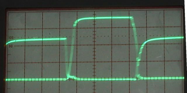
Just if you want to see this are both gates. Both looking from -Vcc
I'll see if this will change any with higher supply voltage.
Bender where do you use your amp and with what load ?
Does it heat up any at full power?
What is your supply (Trafo)?
Just if you want to see this are both gates. Both looking from -Vcc
I'll see if this will change any with higher supply voltage.
Bender where do you use your amp and with what load ?
Does it heat up any at full power?
What is your supply (Trafo)?
Add decoupling capacitor accross your mosfet supply. A good 0.47uF 250V MKT will cure all ringing you have on your squared wave! Some 0.1uF ceramic with 4.7 ohms resistor to ground help a lot too...
Fredos
Fredos
Hi fredos
I have 2x 0.22uF caps, but I don't think they are good for this. Will try to get better one.
I have 2x 0.22uF caps, but I don't think they are good for this. Will try to get better one.
From output to ground?Some 0.1uF ceramic with 4.7 ohms resistor to ground...
Hi, Luka.
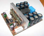
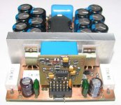
I built this amp for subw, but it applicable for full range. It's only light (small power) version, now i assemble next version of this amp. Effeciency = 93..94%, you can easily calculate heating power.
My PS is classic 250W (~220V 50Hz) torroid with 20000uF capacitor per rail (48V*2 at idle), planned replace it with SMPS.
Hi bender
Effeciency is really high in my too since I can drive 4 ohm speaker with ~70w with no heatsink and fets heat up only about 10C
How do you get other voltages for amp(+/-10v if you have, 12v for fet driver...)
I will skip trafo and go directly on smps, just have to make new board which will have synchronization on it, everything else is already ready.
Hi Luka,
voltage gain is about 36.1dB (so 64.17 voltage amplification...)
Dangerous to push an amp to clipping without any load !
It doesn't mean a thing as well because clipping depends on the load connected...
bye.
voltage gain is about 36.1dB (so 64.17 voltage amplification...)
Dangerous to push an amp to clipping without any load !
It doesn't mean a thing as well because clipping depends on the load connected...
bye.
Hi alexclaire
If with no load doesn't count, I will have to out it on bigger supply, because eveytime there was bass, supply shut down. I think I have burned LM319 while testing current limit.
Why is that?Dangerous to push an amp to clipping without any load !
If with no load doesn't count, I will have to out it on bigger supply, because eveytime there was bass, supply shut down. I think I have burned LM319 while testing current limit.
No, it's classic half bridged amp, i didn't test and measure this amp, maybe tomorrow.
I'm gonna use couple in bridge mode to get 500w RMS at 8Ohm driver.
I'm gonna use couple in bridge mode to get 500w RMS at 8Ohm driver.
Hi
I am sure that you could get that power right now with this modul, just bigger supply voltage, so my question is why don't you? I mean why would you use two moduls if you can get it from one?
I am sure that you could get that power right now with this modul, just bigger supply voltage, so my question is why don't you? I mean why would you use two moduls if you can get it from one?
Because i need 90V per rail minimum, to get such power at 8Ohm load, in that case each of ballast resistors must dissipate ~2.4w..
With couple and 60V per rail, i can easily get 500w of continuous power, and ~900W of peak power at 8Ohm driver.
ps: one module provide ~500w at 4Ohm load, i think enough for home or car subwamp.
With couple and 60V per rail, i can easily get 500w of continuous power, and ~900W of peak power at 8Ohm driver.
ps: one module provide ~500w at 4Ohm load, i think enough for home or car subwamp.
- Status
- Not open for further replies.
- Home
- Amplifiers
- Class D
- D AMP is back !!!