Hi
For home or car that is way too powerfull, but it is all in achieving desired goal. I would like for my to go between 0.5-1kw but have no way of listening that loud, but a goal is a goal. Probably same for you. Keep us posted on further development/measurements
For home or car that is way too powerfull, but it is all in achieving desired goal. I would like for my to go between 0.5-1kw but have no way of listening that loud, but a goal is a goal. Probably same for you. Keep us posted on further development/measurements
Bender.RU,
Have you tested your amp with open load and input subjected to +11dB overdrive signal.....Hard Clipping, also with Full Load ofcourse.....
Have you tested your amp with open load and input subjected to +11dB overdrive signal.....Hard Clipping, also with Full Load ofcourse.....
Bender.ru said:Hi Workhorse, i didn't test it yet.
I'll post all test results later.
but be careful...as it could be dangerous for your amp...to survive
Hi
Could someone show me how does their voltage on current sense resistors looks like when amp at idle
Could someone show me how does their voltage on current sense resistors looks like when amp at idle
IVX, i also think that H-bridge topology more preferably than half-bridged one, that's why i need couple of such module...
Other reason: i never like high (relatively) voltage shematics .
.
Other reason: i never like high (relatively) voltage shematics
.IVX said:Bender, i've tend to love H-bridge 45+45VDC, instead the half bridge with +/-90VDC rails.
How about +-90VDC H-Bridge.....
I'm very interrested in this subject.
For luka, fredos and alexclaire: Please send me the the final version of D-amp schematic and PCB, I mean the Project file from what you are working with: tool, simulating program... (not the print screen of the schematic)
For 'Bender.ru' : what happend to the .ru forum:http://www.vegalab.ru/forum ?? is not working any more. It was interesting by the nr of ClassD schematics
Workhorse said:
How about +-90VDC H-Bridge.....
My last project is H-bridge 380VDC, 80nS dead time, 100kHz, THD nearly zero, but i love lower voltage amps yet.
Hahaha
Hi
Today I found that my overcurrent works, but how I found it to work is funny. Amp was running with + of probe already connected to one side on current sense resistor. And as soon as I touched with - to other side protection activated. This is because everything is connected to same phase from mains and scopes have their GND of channels connected to chassis, making such measurements impossible
Hi fredos
Protection works great, thanks for help
Re: Hahaha
Have you tested Short Circuit with output voltage swinging close to rails or even clipped....on your amp
luka said:Hi
Today I found that my overcurrent works, but how I found it to work is funny.
Have you tested Short Circuit with output voltage swinging close to rails or even clipped....on your amp
Hi
No. I'm scared to do that 😀. Well as long as I have 16A fuse inside I won't try that, but it works with music on speaker.
Does anyone have pic of how does their voltage on current sense resistors looks like when amp at idle?
No. I'm scared to do that 😀. Well as long as I have 16A fuse inside I won't try that, but it works with music on speaker.
Does anyone have pic of how does their voltage on current sense resistors looks like when amp at idle?
luka said:Hi
No. I'm scared to do that 😀. Well as long as I have 16A fuse inside I won't try that, but it works with music on speaker.
But i am not scared of short circuit...due to fast protection....
I donot use Resistors in series with rails or Fets, I rely on current transformer made with output inductor... a few secondary turns on the output inductor facilitates the current sensing without any efficiency loss....
Hi
I haven't come that far jet, but it sounds great. I will give is a try if you can show me /tell em how this works, any pic would be great. I have this resistors, I destrojed 0.1 ones with low output load. I think it was 0.3 and on scope there was 5v
I haven't come that far jet, but it sounds great. I will give is a try if you can show me /tell em how this works, any pic would be great. I have this resistors, I destrojed 0.1 ones with low output load. I think it was 0.3 and on scope there was 5v
Some hints....
There are many options with the current sense transformer....
You could use the isolated secondary windings to do the following:
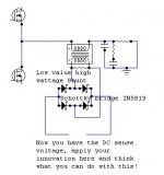
Use a low value shunt and rectify the output by using schottky diode bridge....
1. Limit the input signal or mute
2. Clamp the gate drive signals...or latch the driver IC
3. Turn-off a relay or deactivate any type of crowbar....
There are many options with the current sense transformer....
You could use the isolated secondary windings to do the following:
Use a low value shunt and rectify the output by using schottky diode bridge....
1. Limit the input signal or mute
2. Clamp the gate drive signals...or latch the driver IC
3. Turn-off a relay or deactivate any type of crowbar....
Attachments
Hi
I would put it on input of timer, thus turning off IR. How many turns should I put on, and what resistor?
What about DC??
I would put it on input of timer, thus turning off IR. How many turns should I put on, and what resistor?
What about DC??
luka said:Hi
How many turns should I put on, and what resistor?
Thats your homework!😉
Wind it using 2:1 ratio to get starting...also measure the voltage across it when passing max current through your inductor....
Hint: In my setup i use R shunt=100ohm 5W....
- Status
- Not open for further replies.
- Home
- Amplifiers
- Class D
- D AMP is back !!!