Howdy,
i ran into some problems with my F5c build. Basic info first:
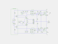
Boards Cvillers F5c V2.1, Cascode, two Output pairs, 35V Rails, current limiting parts arer in place. I atttached schematics for convenience
this is my second F5 Build, the classic one are running fine for nearly a decade now. I am in the process oof initial bias setting. One channel is fine, oon the second channel Q104 seems too draw way more current then Q4. Q104 is also a lot hotter then Q4 The Transistor were bought as matched Sets from a forum member. R12 and R112 are 5% panasonics and not are not matched.
Across R112 i measure 440mV across R12 i measure 550mV, thats a huge difference, even after cooking in the difference stays there, all other voltages across the source resistors are way closer and a good chunk below 10%. Does anybody have a clue where i should start to look for errors? I think i got a spare IRFP240 laying around but that thing is not matched to the other transistors. I suspected the current limiting transistor Q6, but that one is fine and dandy.
i ran into some problems with my F5c build. Basic info first:
Boards Cvillers F5c V2.1, Cascode, two Output pairs, 35V Rails, current limiting parts arer in place. I atttached schematics for convenience
this is my second F5 Build, the classic one are running fine for nearly a decade now. I am in the process oof initial bias setting. One channel is fine, oon the second channel Q104 seems too draw way more current then Q4. Q104 is also a lot hotter then Q4 The Transistor were bought as matched Sets from a forum member. R12 and R112 are 5% panasonics and not are not matched.
Across R112 i measure 440mV across R12 i measure 550mV, thats a huge difference, even after cooking in the difference stays there, all other voltages across the source resistors are way closer and a good chunk below 10%. Does anybody have a clue where i should start to look for errors? I think i got a spare IRFP240 laying around but that thing is not matched to the other transistors. I suspected the current limiting transistor Q6, but that one is fine and dandy.
Attachments
Last edited:
Well that sucks. I took he amp apart, desoldered the N Channel Jfets and matched them at different currents ... yes Q4 and Q104 differ in VGS by up to 0.3 volt 🙁
sadness did overcome my soul, for curiosity i matched my spare IRFP240 and guess what, it matches nearly perfect with a mere VGS difference of 0.03V across all currents. Thanks to the Lord were spoken. Its a different manufacturer, this one is IR the others are Vishay I think. I will report back after assembling everything again.
sadness did overcome my soul, for curiosity i matched my spare IRFP240 and guess what, it matches nearly perfect with a mere VGS difference of 0.03V across all currents. Thanks to the Lord were spoken. Its a different manufacturer, this one is IR the others are Vishay I think. I will report back after assembling everything again.
I've got hand of a blown cascided cviller v2.1 rail 40v amp. Perhaps add gate resistor to q101 and q102 else they oscillate thru c101 and c102? (colpits?)
I've got hand of a blown cascided cviller v2.1 rail 40v amp. Perhaps add gate resistor to q101 and q102 else they oscillate thru c101 and c102? (colpits?)
On my board there are base resistors for q101 and q102 and also additional 1nf caps, booth mods suggested by papa, of course i installed them.
Little update:
even with the new Mosfet and perfectly matched source resistors there is still a huge difference in the voltages across R12 and R112, something is utterly broken in the circuit, anybody got a clue what it could be?
even with the new Mosfet and perfectly matched source resistors there is still a huge difference in the voltages across R12 and R112, something is utterly broken in the circuit, anybody got a clue what it could be?
input is floating, only load on the output is the multimeter. Second channel has no problems measured in the same configuration.
ground input for test
is there a way to check for oscillations ?
if not , install compensation caps across feedback resistors
shoot for , say, 150KHz (F=1/2xPi x R x C)
is there a way to check for oscillations ?
if not , install compensation caps across feedback resistors
shoot for , say, 150KHz (F=1/2xPi x R x C)
Yes, i have a scope to check for oscillation, i will have to lift this beast on the workbench tomorrow.
Did a quick check with grounded input, didnt change a thing. Whats interesting that the difference across the source resistors is the same 110mv as with the initial N Channel Mosfet combination. That could mean that the initial set of Mosfets is indeed well matched (need to desolder and verify, legs did look a little oxidised so i might have screwed up the measurement) and the problem lies somewhere else in the circuit.
Did a quick check with grounded input, didnt change a thing. Whats interesting that the difference across the source resistors is the same 110mv as with the initial N Channel Mosfet combination. That could mean that the initial set of Mosfets is indeed well matched (need to desolder and verify, legs did look a little oxidised so i might have screwed up the measurement) and the problem lies somewhere else in the circuit.
last night I forgot to ask - what was output offset while you were measuring ?
recheck values of feedback resistors , maybe some of them is Dodo
recheck values of feedback resistors , maybe some of them is Dodo
Offset is low, 10mV max and easily adjustable. I was up until 4am yesterday, some other users also had problems with their cviller builds, blowing up only one the Mosfets because of oscillation. Today i will try to insert some resistance between the cascode BJT and Jfets (Papa suggested that several times and also increase the gatestoppers to a higher value. I will report back with my findings later.
It could be oscillation on the output giving odd meter readings.
Your gate resistors are very low, I tend to use 390R's.
Your gate resistors are very low, I tend to use 390R's.
No clues or traces for oscillation at the output or the fet gates. The only AC i can spot is ripple on the rails, Voltages on the transistors measure fine:
Q101/102: C 30.5V B 17.3V E 16.7V
Q104/4: G -30.3V D 15mV S -34.6V
Q6: E -34.8V C -30.4 B -34.7
i am starting to feel a little lost, will swap fets again and see what happens
Q101/102: C 30.5V B 17.3V E 16.7V
Q104/4: G -30.3V D 15mV S -34.6V
Q6: E -34.8V C -30.4 B -34.7
i am starting to feel a little lost, will swap fets again and see what happens
Since you needed to "lift the beast" I guess you have an old slow analogue oscilloscope.
This guy needed his digital rigol to find cascode oscillation problem:
http://hifisonix.com/wordpress/wp-content/uploads/2010/10/Cascode-Oscillation-in-Audio-Amplifiers1.pdf
See also More Notes On Cascode Amplifier Oscillation
Maybe one of grown up in this forum can explain how oscillation can happen
in this concrete circuit?
I found also this discussion
http://audioworkshop.org/downloads/AMPLIFIERS_OSCILLATION_BJT_CIRCUITS.pdf
Can you post a few clean pictures of your build?
Sounds like something is not completely as it should be.
Sounds like something is not completely as it should be.
Little update:
Adding 1nf caps to the base of the cascode BJTs did nothing, adding 1nf across the feedback resistors did nothing. Feedback resistors are measuring fine, took out the replacement IRFP240 and swapped in the old matched one, did nothing.
Next on the list, increase gatestoppers, take pics.
Equipment Info: 2 older Fluke DMMs, a crappy cheapo DMM and a 60Mhz 2 channel analog scope. Signal generator and external soundcard for THD noise measuring (basically to set P3 when everything is running fine)
- Status
- Not open for further replies.
- Home
- Amplifiers
- Pass Labs
- Cviller F5C, vastly different current draw between two IRFP240