the P-Channel is still way better matched but the huge difference we had at the beginning is gone now. I will contact the seller of the mosfets and le him investigate.
As I'm the "seller", I think I better chime in here🙂
I told you I will be happy to investigate if you let me know the IDs of the transistors (they are all uniquely labeled) or if you send them back to me.
However, as you say that: "the huge difference we had at the beginning is gone now", leads me to think that the problem you have is specific to your circuit and that it is not caused by poor FET matching. Certainly the changes you are doing to your circuit can't change the tolerance of the matching😱
To understand if the FETs are poorly matched, you need to measure them out of the circuit under controlled conditions.
Cheers,
Nic
Yes, i think there were other issues too, especially since removing the current limiting circuit did change things. I also changed the BC560C in the cascode when i rremoved them to check for errors. The new one might have smaller GM and that culd have solved the issue, we dont know. The other is channel working fine (have to check again tomorrow) with currrent limiting still in place, so the BC560C is still a suspect to possibly have caused the trouble. However there is still some difference in Vgs. Maybe we are already down to acceptable levels, i wouldnt mind some feedback on this.
Nic, no worries you will get your hands on the fets as soon as i have some replacements and have confrmed we have a matching error. There is other possibilities that need to be investigated first: Two N-Channel fets got mixed up between channels, that could have happened too. You have a curve tracer, right, otherwise the other fets would not match up that precisely.
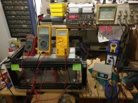
I measured them out of circuit using a constant current source at various currents ranging from 5ma to 700ma. I wont rely on my low current measurements, in the "high" current measurements up at 700ma the Vgs difference is 0.125V. i think the other fets are matched way better.
There is also the possibility that the source resistors dont match. But i tested these with terminal measurement and the mismatch between the voltages is slightly non linear.
Last edited:
Happy to hear that you’re making some progress. I can send you a set of replacement boards if you PayPal me for postage.
Cviller, great, you seem tto have disabled the PM function. Can you drop me a PM with the payment details?
I think the choice of BC560C for the cascode should be discussed. Papa has chosen a tansistor 2SA11837 with vastly lower hFe. 2SA11837 has 320 max, BC560C has 900 max and looking at the frequency curves, the BC560 looks like a prime choice to build a radio frequency oscillator especially in the low current area.
I think the choice of BC560C for the cascode should be discussed. Papa has chosen a tansistor 2SA11837 with vastly lower hFe. 2SA11837 has 320 max, BC560C has 900 max and looking at the frequency curves, the BC560 looks like a prime choice to build a radio frequency oscillator especially in the low current area.
Last edited:
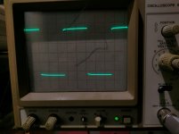
I didnt do much today, just checked the square wave response, 1kHz square wave at 1V out in 8 ohms dummy load, looks good, no signs of overshoot. I will take care of tthe other channel tomorrrow (remove current limiting circuitry and check / adjust bias)) , then some more burn in ... maybe even a listening test 😀
Attachments
Sounds like you are ready to start listening - at least on some test speakers.
I was going through the basement and was not able to find my box of prints, so unfortunately I'll not be able to ship you replacement boards just yet. 🙁
I was going through the basement and was not able to find my box of prints, so unfortunately I'll not be able to ship you replacement boards just yet. 🙁
You want to run 1.25A pr device for a total of 2.5A bias at 35V rails? That's about 44W heat dissipation pr device. That is alot.
Sounds like you are ready to start listening - at least on some test speakers.
I was going through the basement and was not able to find my box of prints, so unfortunately I'll not be able to ship you replacement boards just yet. 🙁
Yes today was the big day. I hooked up both channels to 8 ohm dummys and my external soundcard to set P3 settings were done at 2.6V RMS. I use baudline for all my spectral analysis, sometimes JAA, i miss a log x axis but it does the job well.
Both channels are absolutely identical in THD S/N etc. THD is -86.5dB. Gain difference between channels is 0.05db. I hooked up the amp to my small desktop speakers, no turn on hump no noise no nothing, just music. Nice. So i hooked eveything up to my living room speakers (JBL TI5000). Oh boy, whats that fuzzy noise, that sounds like F interference... well, turns out hooking up your pc via a 3 euro switchbox and 6 meter line cables of the cheapest thrift store variety can upset your preamp a little. Switching to another input on the preamp revealed that he amp is silent. The amp really is fine, first impressions, yep its an F5 just a little better. Remember i have my original F5 Monos for nearly 10 years now.
What really strikes me is that the sound is a litle less glued to the speakers, i had T&A Criterions before the JBLs and was missing some of the space and atmosphere the T&As had. Even with the F5c as a stereo amp you can feel the space again. I am really pleased.
Temperature is already at the limits and thats with a single 120mm fan for both heatsinks. These are chunky heatsinks, with very tight structured fins so they have to be cooled with forced airflow, especially since the are perpendicular to the botttom of the case. Under no chance will this work in a closed case, even with giant ventilation openings. I will experiment with different fan configurations, i think i will go with one 140mm for each heatsink and maybe move the heatsinks to the left and right side. The base structure of the amp is aluminium profile, so its very easy to work with different panels made from cheap plywoood. Aluminium panels will be installed when everything works fine. I crank up the bias to 1.1A max.
Cviller just drop me a line if you stumble upon the pcbs, for now i have jjust soldered the resistor directly to the gate f the fet.
There is still the unsolved mystery with the N Channel fets. Might be the the source resistors.. although matched at room temperature the may drift in different directions, difference between the fets is less then 10 percent, i will investigate this later on, case and temperature control has priority right now.
Might split this one up and build monoblocks and VU Meters... i see large VU meters and walnut veneers, dont judge me, i am child of the 80s.
What i am most proud of is that thing is done much more safe then my old F5s, correct grounding, heatshrink everywhere and safety earth and circuit earh connected directly withouty any audible hum.
I will keep you guys updated, its really great to have some experienced people to learn from, thank you all.
Last edited:
Congrats!
How close are you matching source resistors R12 to R112 and R11 to R111? I expect they should be as well or better matched as the mosfets?
How close are you matching source resistors R12 to R112 and R11 to R111? I expect they should be as well or better matched as the mosfets?
Congrats!
How close are you matching source resistors R12 to R112 and R11 to R111? I expect they should be as well or better matched as the mosfets?
Howdy,
yes the source resistors were tightly matched using a constant current source. BUT, yes there is a BUT, matching was done at 100ma current. This means there is room for error, TC related error in particular.
General Update:
I have been running the amp for several weeks now, heatsink temperature is stable at 44°C. I measure this with one DS18b20 mounted in the center of each heatsink between the transistors. This is with the cheapest 120mm fans i had in my parts bin mounted on the heatsinks. These will be updated to 140mm. Case is still not finished, but i think i can do the final bias adjustment soon. I will throw in a cheap fan control so i get faster heat up. A very simple "Run fans at full speed when temperature reaches X" program is more then enough t achieve this. Circuit will be powered bby an auxiliary transformer, maybe a switchmode supply but definately isolated from the main power supply.
All in all its running fine without any problems, sounds great and i really like it.
Since snubbering the transformers is the new hype i might look into that, but to be true i dont really care at the moment. A nice looking case has priority right now. I got me router last week but cant decide on the veneer for the side panels.
- Status
- Not open for further replies.
- Home
- Amplifiers
- Pass Labs
- Cviller F5C, vastly different current draw between two IRFP240