Also...
"Is it possible to do that in 4mm aluminium by drilling lots of small holes on the inside of the shape and then sanding & filing it out?"
Yes. In fact, earlier in this thread (look for "chain drilling") a couple guys (more like Gods, really) detail the entire process in a truly informative, witty, and exhaustive (some might say "tedious") manner.
Read up, and then send them lots'a money (right, Steve?). 😀
E
Re: Dh
When I eventually end up in the hardware store I'll pick the heaviest (but not over the top 😉) standoff I can find. I'm pretty sure it will hold it's shape, because the parts of the pannels extended over the heatsinks will make it a lot harder to bend the construction sideways. Also, I find it pretty hard to bend the aluminium a lot, altough it's 1m by 1m, it should be even harder to bend them when they are smaller.
It's clear, thanks 🙂!
Well, I haven't got anything, but a friend of mine does. Actually, the reason I started thinking of getting this CNC'ed is that he hasn't got an aluminium blade for his table saw (well, he has one, but it's broken). I could buy him an aluminium blade if it isn't too expensive. I figure I'll have to use some of his other tools or getting it done somewhere else if it's too expensive. Anyway, all that doesn't matter. I can drill at 90° with a drill press, making a guide shouldn't be too difficult.ekd said:...The secret to going "dead nuts" is having the ability to drill at a perfect 90 (got a press? Guide?), drilling a slightly smaller hole, then reaming it to size. You don't need to get that fussy, but if you take the time to do it this way, and just use a good bit (gently) instead of a reamer... You will see a difference.
I don't doubt that you will do a fine job, I just have experience with enclosures that rely on panels to keep them square. They have to be assembled loosely, then tightened up. The real reason for going with heavier standoffs is that you will be working with this box without those last two panels... and the small dia standoffs wiill try to bend the screws if you flex the box.
If the box will hold it's shape (stay square) without the panels, the entire process will be much easier, and much less precision is needed on the panel holes.
Hope this helps (hope it's clear?)...
When I eventually end up in the hardware store I'll pick the heaviest (but not over the top 😉) standoff I can find. I'm pretty sure it will hold it's shape, because the parts of the pannels extended over the heatsinks will make it a lot harder to bend the construction sideways. Also, I find it pretty hard to bend the aluminium a lot, altough it's 1m by 1m, it should be even harder to bend them when they are smaller.
It's clear, thanks 🙂!
It's not the just the bending...
It's the accumulation of lost tolerances.
As a kid, a surveyer taught me the concept when I asked him why he was so concerned with such precision, even out in the woods.
He explained that if he didn't keep the tolerances, and the losses continued to add up as they went west (from Michigan), someone in California would suddenly find themselves without any property. Not quite true... Bad tolerances go both ways, but he made his point.
If you rely on the mating of the material being (and staying) square (standoff to sink), instead of your hole placement, you will be happier with the result. Fasteners are for clamping, dowels are for alignment...
It's gonna be sweet, D. The care you are putting into it now will not only ensure that it will always make you proud, but the habits you develop now will show in all your future work.
E
_____
Post. Edit. Edit again. Hit the report button while trying to edit a third time. Report yourself as a moron.
Re: It's not the just the bending...
Thanks for the nice comments 🙂. I've still got a massive ammount of things to learn though.
Ok, so making sure that the hole is drilled at 90° is more important than making sure it's dead center.ekd said:It's the accumulation of lost tolerances.
As a kid, a surveyer taught me the concept when I asked him why he was so concerned with such precision, even out in the woods.
He explained that if he didn't keep the tolerances, and the losses continued to add up as they went west (from Michigan), someone in California would suddenly find themselves without any property. Not quite true... Bad tolerances go both ways, but he made his point.
If you rely on the mating of the material being (and staying)square (standoff to sink), instead of your hole placement, you will be happier with the result. Fasteners are for clamping, dowels are for alignment...
It's gonna be sweet, D. The care you are putting into it now will not only ensure that it will always make you proud, but the habits you develop now will show in all your future work.
E
Thanks for the nice comments 🙂. I've still got a massive ammount of things to learn though.
Argh, to late to edit my last reply. I guess I'll have to add a new one.
Regarding PD's suggestion of making the top & bottom plate smaller to allow for more air flow. How about these ventilation slots? It'll be a lot of work to make these manual (29 each side; total = 29 x 4 = 116 😱), but 3 months of summer vacation should be enough 🙂. The slots are between the fins of the heatsink, leaving 1mm overhang over each side of the fins (a bit for the holes most to the side of the amp, because the fins get thinner the farther they are to the edge of the heatsink).
Regarding PD's suggestion of making the top & bottom plate smaller to allow for more air flow. How about these ventilation slots? It'll be a lot of work to make these manual (29 each side; total = 29 x 4 = 116 😱), but 3 months of summer vacation should be enough 🙂. The slots are between the fins of the heatsink, leaving 1mm overhang over each side of the fins (a bit for the holes most to the side of the amp, because the fins get thinner the farther they are to the edge of the heatsink).
An externally hosted image should be here but it was not working when we last tested it.
An externally hosted image should be here but it was not working when we last tested it.
"Ok, so making sure that the hole is drilled at 90° is more important than making sure it's dead center." God, no! If C thinks I left you with that impression, he'll sentence me to having my "sixth finger" milled off, and permanent banishment... 😱
What I'm saying is that if you use the relationship between the mating surfaces to keep things square (and wider means squarer/stronger), and only rely on the fasteners to clamp them together, you will be able to drill the holes big enough to allow easy assembly (and not have to worry about accumulation.
Maybe think of it this way... Design and cut your parts as if you were going to glue them together. If they fit squarely together the fastener's holes will not have to be so precisely sized/positioned. Make them fairly precise, and you will enjoy easy assembly (and it will make you proud when putting in a couple of screws.. and suddenly all the other holes line right up). As you develop your skills, you will find that making the really small stuff is not as hard as it used to be.
Guys? Help us out here. I may be doing more damage than good, and if you can put this in a way that makes more sense, you will do us both a favor.
We all have massive amounts to learn. If this wasn't true, I'd have already become bored, and wandered off...
D, let's keep trying... This is all a result of my lack of com skills, -not- a reflection on your intelligence. I have a lot of confidence in what will be your final results
E
D
The vents look nice. And the drawing is superb. and...
If anyone asks what you did over the summer, you will have something nicer to show them than a bail receipt or an STD...
You won't have time to get into trouble... 🙂
E
The vents look nice. And the drawing is superb. and...
If anyone asks what you did over the summer, you will have something nicer to show them than a bail receipt or an STD...
You won't have time to get into trouble... 🙂
E
Missed my edit window again...
D, if you simply drill holes, where pic indicates, you will open up the heat trap formed in the corner. It'll vent completely, and take very little time.
When form follows function, the piece will naturally look good. And the precision of the holes (that don't need hand finishing) will look better than anything you can do without a mill (one crooked vent, and it is all you will see when you look at the top. Trust me, even if no one else notices...).
Maybe draw it up, and consider it? Or, put half as many bigger holes, centered on every other fin... Polish the fin, and give us all something to look at inside the hole?
E
Attachments
ekd said:"Ok, so making sure that the hole is drilled at 90?is more important than making sure it's dead center." God, no! If C thinks I left you with that impression, he'll sentence me to having my "sixth finger" milled off, and permanent banishment... 😱
What I'm saying is that if you use the relationship between the mating surfaces to keep things square (and wider means squarer/stronger), and only rely on the fasteners to clamp them together, you will be able to drill the holes big enough to allow easy assembly (and not have to worry about accumulation.
Maybe think of it this way... Design and cut your parts as if you were going to glue them together. If they fit squarely together the fastener's holes will not have to be so precisely sized/positioned. Make them fairly precise, and you will enjoy easy assembly (and it will make you proud when putting in a couple of screws.. and suddenly all the other holes line right up). As you develop your skills, you will find that making the really small stuff is not as hard as it used to be.
Guys? Help us out here. I may be doing more damage than good, and if you can put this in a way that makes more sense, you will do us both a favor.
We all have massive amounts to learn. If this wasn't true, I'd have already become bored, and wandered off...
D, let's keep trying... This is all a result of my lack of com skills, -not- a reflection on your intelligence. I have a lot of confidence in what will be your final results
E
I think I understand what you mean, and here is my problem. Since I am building a rectangular box like
this (picture 6 and 9 will tell u what I mean), and using angle to hold up each corners. However, drilling only big holes to like it free to abjust is not working because it is hard to drill and accurate holes that is with less than 1/16" error without clamping it. How can I hold the panels in place, and use it as guide to drill an accurate hole that will make the chassis more even? I already drilled the panel, but I messed up on the angle already that make the front panel slightly moved noticably to the left 1/16". Man, I can't think og a way to clamp it in place since panels are pretty lengthy.
Or cut it to hang 1/4" or so over the base of the heatsink and file a pretty chamfer on the edge. Anything covering the edge will impeed natural convetion and the "chimney effect". But it really won't matter unless this chasis is for Class A. If so, every little bit counts.
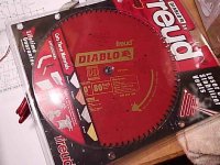
Freud makes a special " Non Ferrous Metal Blade" that can be got for that price and this blade is designed only for non ferrous metals. That's what I've been using all the time. I bought mine from Busy Bee Machine, but I believe it can be also obtained from HD or Rona on a special order, if not available off the shelf.
I have no experience with that red Diablo blade, although it may be very good.
I have no experience with that red Diablo blade, although it may be very good.
Devil!
Stop Now!
OK everything you've been told is true ~ from Peter regarding convection and from Ed on drilling.
But...
Don't do those slots. They will be VERY difficult to get correct. You can always take it apart and do them later if's a Class A room heater. The difficulty on slots is that the tool wants to move one way or the other so the slots look like big "commas" to the eye. The eye can easily discern a distorted pattern in the range of ~.2 or .3 mm. Also, every time you cut a hole it needs to be deburred or chamfered, each step is a possibility for a mistake.
Next item...
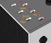
Hole clearance~ there are two standards here in the USA, "close fit" and "free fit". There is surely something like close and free in metricville.
In round numbers, close and free are 3% and 6% (respectively) over the nominal fastener size. So a close fit on a 6mm fastener would be 6mm +(3%*6mm)=6.18 mm ~ 6.15 mm. A free fit would be about 6.35 mm. Forget about getting a 6mm fastener into a 5.5mm hole. You would need a BIG HAMMER!
Drilling holes. There is no way to get a hole in position without giving it some method of starting in that position. Without a little help, the drill moves .5mm to the side and then starts downward. BAD!
There are three ways of getting the drill not to "walk" (move laterally before "digging in").
1. Punch the hole location with a sharp object leaving a small crater that the drill will not walk out of.
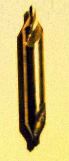
2. Use a "center drill". This is a drill with a very shallow included angle on the tip that prevents it from moveing laterally. It is only meant to drill 2-3 mm deep. It is used to start a standard twist drill.
3. Use a drill with some sort of "special" point geometry... a split point drill. This is a drill where the chisel point is ground to eliminate the typical flat spot on a the drill tip.
In most cases, all that is needed is a healthy whack of a hammer on a sharpened punch to produce a spot where the drill will start and not go sideways. This is even necessary when drilling on a rigid press or mill if you are using a conventional drill point. The drill will certainly move outside the boundries that we have established for a "close fit" and perhaps even a "free fit".
If you have the holes in the panels, we would typically use a thing called a "transfer punch" to mark the spots for drilling on the heatsinks. The transfer punch is the diameter of the drilled hole in the panel.... very close fit ~.1mm, and it has a sharp point on the end. You put the punch through the hole of the panel, touching the heatsink. Hit it with a hammer and it will leave a small mark on the heatsink where the next hole may be drilled and then tapped.
Sailing was good tonight! 15 knots Westerly, 73 degrees. A few minutes later, 35 knots northerly, 51 degrees. We call this a dry squall, no rain, sometimes a hozontal roll cloud. Anyway, back in the harbor just in time.
Stop Now!
OK everything you've been told is true ~ from Peter regarding convection and from Ed on drilling.
But...
Don't do those slots. They will be VERY difficult to get correct. You can always take it apart and do them later if's a Class A room heater. The difficulty on slots is that the tool wants to move one way or the other so the slots look like big "commas" to the eye. The eye can easily discern a distorted pattern in the range of ~.2 or .3 mm. Also, every time you cut a hole it needs to be deburred or chamfered, each step is a possibility for a mistake.
Next item...
Hole clearance~ there are two standards here in the USA, "close fit" and "free fit". There is surely something like close and free in metricville.
In round numbers, close and free are 3% and 6% (respectively) over the nominal fastener size. So a close fit on a 6mm fastener would be 6mm +(3%*6mm)=6.18 mm ~ 6.15 mm. A free fit would be about 6.35 mm. Forget about getting a 6mm fastener into a 5.5mm hole. You would need a BIG HAMMER!
Drilling holes. There is no way to get a hole in position without giving it some method of starting in that position. Without a little help, the drill moves .5mm to the side and then starts downward. BAD!
There are three ways of getting the drill not to "walk" (move laterally before "digging in").
1. Punch the hole location with a sharp object leaving a small crater that the drill will not walk out of.
2. Use a "center drill". This is a drill with a very shallow included angle on the tip that prevents it from moveing laterally. It is only meant to drill 2-3 mm deep. It is used to start a standard twist drill.
3. Use a drill with some sort of "special" point geometry... a split point drill. This is a drill where the chisel point is ground to eliminate the typical flat spot on a the drill tip.
In most cases, all that is needed is a healthy whack of a hammer on a sharpened punch to produce a spot where the drill will start and not go sideways. This is even necessary when drilling on a rigid press or mill if you are using a conventional drill point. The drill will certainly move outside the boundries that we have established for a "close fit" and perhaps even a "free fit".
If you have the holes in the panels, we would typically use a thing called a "transfer punch" to mark the spots for drilling on the heatsinks. The transfer punch is the diameter of the drilled hole in the panel.... very close fit ~.1mm, and it has a sharp point on the end. You put the punch through the hole of the panel, touching the heatsink. Hit it with a hammer and it will leave a small mark on the heatsink where the next hole may be drilled and then tapped.
Sailing was good tonight! 15 knots Westerly, 73 degrees. A few minutes later, 35 knots northerly, 51 degrees. We call this a dry squall, no rain, sometimes a hozontal roll cloud. Anyway, back in the harbor just in time.
Peter Daniel said:Freud makes a special " Non Ferrous Metal Blade" that can be got for that price and this blade is designed only for non ferrous metals.
<snip>
I have no experience with that red Diablo blade, although it may be very good.
I'm sure the Freud non-ferrous is better, especially for the money. That said, I have the red Freud 60T and it cuts aluminum like butter.
From Devil's drawing I think he may have a hard time to use a drill press on that heatsink. I had similiar situation before either the chunk is too big that it gets in the way or needing a very very long drill bit and hope it does not do the walking. The most challenging task that he will face I would think is the precision of all the holes alignments. With each increasing mm in length of the stand off the more precise each has to be. And there are 24 holes. That means out of 12 holes if 1 is missed then that side is some what ruined. A tough task and very high standard he is aiming for. I wish him best of luck.
Chris
Chris
Irrespective of any one case, the thing to remember about drill length is that they -all- flex and they all walk. The center drill that C refered to (shown) is shaped to eliminate as much as possible, and it's only job is to start the hole.
Let's put it this way... A hole that is made with a 8" drill, and prepared the way C says, will be twice as fine as one done with a 1" bit on an unprepped surface. Every time.
E
Let's put it this way... A hole that is made with a 8" drill, and prepared the way C says, will be twice as fine as one done with a 1" bit on an unprepped surface. Every time.
E
Attachments
Chris
The blades made for non ferrous metals are tripple chip with a neg rake. This means the teeth alternate between square tooth and square tooth with the corners ground off. The negative rake means that the facet of the tooth more or less parallel with the radius is leaned back to not dig in.
The typical "alternate bevel tooth" blades that have one tooth angled to the left and one angled to the right tend to flex the blade back an forth as they cut and bake the blade wobble and make a rough cut. The ones with positive rake tend to try to dig in and self feed.
80 tooth for a 10" is pretty good.
One bit of advice on cutting extrusions. (I have professional experience here) Cut so the blade first contacts the loose end of the extrusion. Also cut so that the loose end will disengage the blade when it flexes. And if your saw has a brake, bee sure you are all of the way through your cut before you release the switch.
Good luck and keep your fingers.
Upon closer inspection of your pic, I think that you have a decent blade. Freud makes some nice ones. I can see that it's recomended for Alu, brass, and copper. tripple chip and looks neg rake. Cut away
- Status
- Not open for further replies.
- Home
- General Interest
- Everything Else
- Cutting, drilling, mounting etc. for the absolute beginner