Peter...
Again, you have given me a level of comfort (in what, to me, is entirely alien territory) that is keeping this whole learning process fun.
It would have never occurred to me that pouring a conductive material through the center of a torroid would create a "core". I was eventually going to find out the hard way...
M is right, but I didn't understand why... Hence the name...
E ('lectrotard)
Thats what I tried to explain in the earlier posts...hence the strong warning against aluminium foil wrapping as well.
Magura🙂
Magura🙂
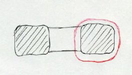
Just to make it clear for everybody. This is a cross section of toroid. You can't create a loop, either with chassis parts or any conductive potting compound, that goes through the center and is closed around the core (like shown with red line).
http://www.diyaudio.com/forums/attachment.php?s=&postid=400857
Otherwise, you can wrap it with aluminum foil and nothing should happen.
http://www.diyaudio.com/forums/attachment.php?s=&postid=400857
Otherwise, you can wrap it with aluminum foil and nothing should happen.
Attachments
tiroth...
" I have been wanting to try out DIY potting but hadn't wanted to spring for mail-order chemicals."
I hear ya!
I'm also always looking for "cheap and readily available" alternatives. I'm not afraid to spend money, but have a serious aversion to wasting it.
Please share anything you learn about the stuff. It is invaluable around the shop, and body guys will always assure a good and cost effective supply chain.
M, I thought you meant that it wouldn't work even if it didn't go into the hole. P's post simply made this clear... even to me (and that ain't easy!).
Let's call this one confirmed! 🙂
E
I hope to get the panels CNC cut, so having ventilation slots in the panels shouldn't be a problem. Thanks!Peter Daniel said:Those bolts should be OK to hold the bottom plate and whole chassis together. What I wouldn't adviise is covering the fins with bottom and top panels, as this reduces the heat dissipation efficience. Unless of cource, you are building chip amp and then it doesn't matter😉
But wouldn't the side/horizontal forces be eliminated by the front/back panels that are attached to the heatsink with bolts too? How exactly would you attach the top/bottom plates then? I don't really get it. You suggest to use a metal tube spacer, what exactly is that?chris ma said:Hello,
May be M6 is strong enough I do not know. But I just see that the way your planning really rely on the bolts strength to take care of all forces not just vertical pulling off the threads. Now your heatsinks can be acting like a lever to bend all the bolts if enough side/horizontal/angled forces rather then just vertical downward force. To bend a screw or bolt with the help of a lever is very easy. I am no enigneer just day to day common sense of diy taught me this particular thinking when bolt metal together at right angles.
IMHO
Chris
Just for clarity, here's a newer & clearer image of how it might look once finished. If you look really good you can see 2 holes in the right heatsink, that's of course where the back panel will be attached. Yes, there's lots of PCBs in there, but that shouldn't be a problem, I still have a lot of space to stack them if it should be necesarry.
Attachments
What is the purpose of the "bars" on the sides of the heat sinks. Are they part of the heat sink?
I believe you would achieve a more rigid structure by using aluminum angle for the heat sink and the bottom/cover. I think the standoffs on the bar lack any lateral stiffness.
I believe you would achieve a more rigid structure by using aluminum angle for the heat sink and the bottom/cover. I think the standoffs on the bar lack any lateral stiffness.
"But wouldn't the side/horizontal forces be eliminated by the front/back panels that are attached to the heatsink with bolts too? "
Only if those bolts have zero slop (not easy to do). If the standoffs are as large as possible (OD), they will translate the bending forces into pulling (tensile) forces. Maybe enough...
Nice drawings!
E
Only if those bolts have zero slop (not easy to do). If the standoffs are as large as possible (OD), they will translate the bending forces into pulling (tensile) forces. Maybe enough...
Nice drawings!
E
He might use bigger dia for the standoffs and that will increase stiffness. But as long as he's using front and rear panels attached with screws to heatsinks, this provides enough vertical and horizontal stability. Bottom and top plates prevent "warping" (as long as standoffs are at least 1/2' in dia..
It seems like the heatsing bars are part of the extrusion.
It seems like the heatsing bars are part of the extrusion.
There appears to be a wide range of polyester resins, and Bondo is simply specified as containing "styrene" on the MSDS, so it is a little hard to say...but in general, it seems that while the resins may have glass temperatures as low as 60-70C they are still safe up above 100C as long as mechanical stiffness isn't required.
I found this on a boat-repair page:
"Polyester resins, even when of poor quality, should not be adversely affected at temperatures below 130°C. Good quality resin should be safe at temperatures far higher than this."
The filler in Bondo appears to be Talc.
Thermal conductivity of (in W/m-K)
Air - ~0.03 @ 80C
Polyester resin - 0.15-0.2
Talc - ?? soapstone is > 2
For reference
Epoxy resin: 0.2
Looking pretty good actually!
It's a GO!
Thanks, T! It's always nice when the facts concur with experience.
Here goes...
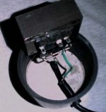
Pipe is cut, the interior is roughed up with 50 grit (better adhesion to Bondo), and holes are punched. A thin floor is poured (should'a done this to the first one, trans settled to bottom during pour). 14 guage solid copper wire bridges input coils, fuse holder is installed, and everything is solidly attached and then soldered.
More soon... 😀
E
Thanks, T! It's always nice when the facts concur with experience.
Here goes...
Pipe is cut, the interior is roughed up with 50 grit (better adhesion to Bondo), and holes are punched. A thin floor is poured (should'a done this to the first one, trans settled to bottom during pour). 14 guage solid copper wire bridges input coils, fuse holder is installed, and everything is solidly attached and then soldered.
More soon... 😀
E
Attachments
Hm, yes, I thought about L-angles too. However, how would I fasten things then? It looks to me that there will be no way to fasten the last bolt & nut, since I won't be able to hold the nut under the panel in place once the case is closed. I'm probably wrong (again 😉).chipco3434 said:...I believe you would achieve a more rigid structure by using aluminum angle for the heat sink and the bottom/cover. I think the standoffs on the bar lack any lateral stiffness.
Sure, go ahead 🙂. Actually, the PCB above the toroid is my power supply PCB for the JLH amp itself. The round cilinders underneath are the bif buffer caps.chipco3434 said:I will be stealing your idea of mounting the rectifier board on top of the toroid.
What do you mean by zero sloping? The OD can be quite large, but I guess it's limited by the ID right? Unless I make them myself of course...ekd said:...Only if those bolts have zero slop (not easy to do). If the standoffs are as large as possible (OD), they will translate the bending forces into pulling (tensile) forces. Maybe enough...
Nice drawings!...
The drawings are made with SketchUp. The only problem with it is that I can't model engraved text, so I guess I'll have to remodel everything in AutoCAD or something eventually if I want to have it CNC'ed 🙁.
I guess you have a lot of experience with these kind of things, so let's see... Are there 1/2" OD standoffs available with an ID around M6-M8? I don't want to use super bulky screws, especially not on the top plate, it will just make things ugly.Peter Daniel said:He might use bigger dia for the standoffs and that will increase stiffness. But as long as he's using front and rear panels attached with screws to heatsinks, this provides enough vertical and horizontal stability. Bottom and top plates prevent "warping" (as long as standoffs are at least 1/2' in dia..
It seems like the heatsing bars are part of the extrusion.
Yes, the extrusions are part of the heatsink. Check my website or www.conradheatsinks.com.
They might be available but I've never seen them like that. I would just do my own from 1/2" aluminum rod by drilling and tapping the holes at each end.Devil_H@ck said:
I guess you have a lot of experience with these kind of things, so let's see... Are there 1/2" OD standoffs available with an ID around M6-M8? I don't want to use super bulky screws, especially not on the top plate, it will just make things ugly.
I never considered nuts 'n bolts. I would suggest drilling and tapping.
As for the CNC stuff. It's not a CNC job if I would interprit it. It's hole drilling and can be done most cheaply by "laying out" (scribing X-Y coordinates on the plates). By the time you lay it out and drill it, you just might get a CNC program to test run. Even if I had the program witten already, I would still do a layout just to make sure that I was drilling at X1.0000Y1.0000-Z1.000 and not X1.000Y1.0000-Z10.000. There is a significant difference. Women worry about missing a period. So do machinists!
As for the word "slop", that means large tolerance as in "sloppy fit". A fit that is looser than normal. Zero slop is a tight tolerance, i.e., "dead nuts".
For standoffs, go look in the little bins at the hardware store. At our store they sell #4 thru 3/8" ID in a variety of lengths. Surely you will find something close.
Slop.
It is also the accurate definition of what I eat, when I'm hanging around here.
I love to cook, but I like this better!
I used a flexible term strip for the outputs, triple checked everything, and poured.
Got a few minutes before the Bondo is ready for rough shaping... Just enough time for a can of something...
E
Attachments

Twisted Metal
I just got in another order of aluminum for my projects, and like the order before that from a different vendor, I got a lot of warped pieces! The strange thing is that all the thinner stuff is perfectly flat (.25" plate and .19" sheet), but the thicker materials I ordered (.375" and .5" extruded rectangular bar, from 2.5" wide to 10" wide) is all warped to some degree.
Is this typical? Also does getting a different type of stock make it more likely to get a warped piece (i.e. plate vs rect bar)? Or should I just find yet another vendor??
I spotted some M6 standoffs with 16mm OD in the Farnell catalogue, but they don't look that strong. Getting a friend of mine to make me some shouldn't be a problem though.Peter Daniel said:They might be available but I've never seen them like that. I would just do my own from 1/2" aluminum rod by drilling and tapping the holes at each end.
For the current layout, I might just as well drill & cut it indeed. Hm, and since I don't really plan on doing fancy stuff, that might be indeed better & faster than getting it CNC'ed & having to learn AutoCAD in the process 🙂.chipco3434 said:I never considered nuts 'n bolts. I would suggest drilling and tapping.
....
As for the word "slop", that means large tolerance as in "sloppy fit". A fit that is looser than normal. Zero slop is a tight tolerance, i.e., "dead nuts".
For standoffs, go look in the little bins at the hardware store. At our store they sell #4 thru 3/8" ID in a variety of lengths. Surely you will find something close.
K, about the slop. If I were to drill, let's say, a 5.5mm hole then try to put an M6 though it, it won't be very sloppy, right? I could make the hole wider if necessary. It's 4mm thick aluminium. Why do you think it would be sloppy? There are 4 screw holes in the front & back pannel, won't they compensate for each other if one were a bit to wide? And wouldn't the 2 holes in each side of the heatsinks compensate for this too?
I need screws & stuff too, so I guess a trip to the local hardware store is a good idea 🙂.
Oh, one more question though. About ventilation slots. Let's say I want rectangular slots, with curved corners, like this:
Code:
 _____
(     )
¯¯¯¯¯Is it possible to do that in 4mm aluminium by drilling lots of small holes on the inside of the shape and then sanding & filing it out?
Id throw the bars right back in their face if theyre warped. Anything over 1.5mm per meter is outside the ISO standards. Naturally the vendor may have expressed in their "conditions" that they dont adhere to ISO standards, then its just tough luck...find another vendor.
Magura🙂
Magura🙂
Dh
"K, about the slop. If I were to drill, let's say, a 5.5mm hole then try to put an M6 though it, it won't be very sloppy, right? I could make the hole wider if necessary. It's 4mm thick aluminium. Why do you think it would be sloppy? There are 4 screw holes in the front & back pannel, won't they compensate for each other if one were a bit to wide? And wouldn't the 2 holes in each side of the heatsinks compensate for this too?"
The secret to going "dead nuts" is having the ability to drill at a perfect 90 (got a press? Guide?), drilling a slightly smaller hole, then reaming it to size. You don't need to get that fussy, but if you take the time to do it this way, and just use a good bit (gently) instead of a reamer... You will see a difference.
I don't doubt that you will do a fine job, I just have experience with enclosures that rely on panels to keep them square. They have to be assembled loosely, then tightened up. The real reason for going with heavier standoffs is that you will be working with this box without those last two panels... and the small dia standoffs wiill try to bend the screws if you flex the box.
If the box will hold it's shape (stay square) without the panels, the entire process will be much easier, and much less precision is needed on the panel holes.
Hope this helps (hope it's clear?)
E
Edit: M is right. I'd be pi$$ed... Give your supplier a chance to make it right. If they don't, dump 'em, and tell the world (or, at least warn us).
- Status
- Not open for further replies.
- Home
- General Interest
- Everything Else
- Cutting, drilling, mounting etc. for the absolute beginner