I'm looking for some advice how to properly apply thread to a brass rod. The dia of the rod is 5.96mm and I'm attempting to make M6 x 1 thread. I'm doing it by hand, but for some reason I can't start it properly with a die I'm using. Is this too big dia of the rod, or is it something else that I'm missing😉
Tired old die? It's only 1/4" so the flats that need taking out on the peaks of the thread (that will have to be removed by the die in your case as it's almost 6mm as it is) shouldnt be too much of a problem. If it was bigger this can be a problem though
Steve
Steve
Nice. 🙂
I usually connect the phonos directly to the case, and also use that point to connect the mains ground, (not the trannie centre tap), to the case. I find this the best way of minimising earth loops.
I usually connect the phonos directly to the case, and also use that point to connect the mains ground, (not the trannie centre tap), to the case. I find this the best way of minimising earth loops.

It's channel.
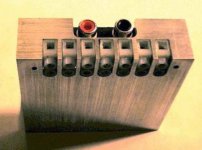
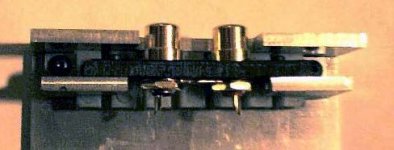
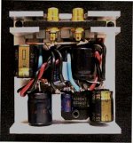
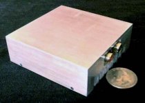
3" x 3" x 1" 6063. Clamshell. It's cut to form a light press fit, so it will spread the heat. Solid billet would just make a bigger mess, there really isn't room for thicker walls ( the top literally clamps stuff down when attached).
It will make a pretty sweet monoblock case, but fitting 2 channels in takes pretty tight machining (the RCAs -just- fit). Would be perfect for active speakers, it'll fit anywhere.
Psu next, then heat it up, and hunt down the ultimate vent pattern.
Gonna need more help soon... 🙂
E
Potting transformers
I read up on it, I want to see just how quiet a psu can be, and one of the suggestions was to use poly resin with up to 70% inert fill.
Sounded a lot like Bondo...
Took a trans (200VA, 20V) with a bit of hum, and stuck it in a piece of 4" ABS pipe, and filled it with a couple bucks worth...
I'm ****ed at myself! It works great! To "hear" the hum, you have to put the unit against your cheekbone. The heat, what little there is, is nicely spread. The problem?
I was going to sacrifice the trans for the knowledge, and now I have a great supply that looks like $hit!
A few minutes spent making it look good (too late now!), and I would not have to hide the thing. Time to make one that I'm not ashamed to show you guys...
Mini-moral: It's a hobby... take your time... you never know when an experiment might just turn into a finished product.
😱
E
BTW
The more fill the resin has, the less it shrinks.
My reading, so far, on this leads me to believe that only power transformers should be potted. Their performance will not be affected by the clamping forces generated by the shrinkage, and benefit (much reduced and damped vibration) from them.
E
The more fill the resin has, the less it shrinks.
My reading, so far, on this leads me to believe that only power transformers should be potted. Their performance will not be affected by the clamping forces generated by the shrinkage, and benefit (much reduced and damped vibration) from them.
E
Attaching Pannels
A friend of mine gave me some new idea's on how to attach the front, back, top & bottom panels to the heatsinks of my soon-to-be JLH (I hope 🙂).
Would this be a good way? (check the attached image)
The top & bottom plate would be attached to the heatsink with screws that go into stand-offs. The gold coloured things in the image are the stand-offs, the screws aren't there yet. I'm thinking M6 for the screws, will that be enough? I guess that the amp will weight a maximum of 15 kgs when it's finished.
Also in the picture, you can see a small plate, mounted with short stand-offs on the bottom plate. It would be attached the same way as the top & bottom plate. 3 screws on each side. I'd like to mount all PCBs on this, so that I don't have to drill all the holes in the bottom plate. The only think I don't know, is what thickness this "mounting" plate should be? I need to mount 2 torroids on it, I guess they weight +- 3kg together. Would a 1mm aluminium be OK, or should I go for something else?
I guess mounting the front & back panel with 4 M6 screws into the sides of the heatsinks is fine?
Attachments
IMO the way to mount the bottom plate you are planning may not work well. Imaging all the weight resting on the bottom plate plus heatsinks themselves, and you lift it up with just six small screws with small diameter and limited threads. Why not use 4 bigger bolts with metal tube spacers go all the way from the bottom of the bottom plate to the surface of the lower extrusion of the heat sinks.
Regards,
Chris
Regards,
Chris
Ok, thanks! Anyway, I had another idea. What if I used 1mm thick alu. It wouldn't be a problem for the PCBs, since they weight virtually nothing. The transfos would be mounted onto this thin plate, but a bolt with a thick nut would go through the plate and thus the transfos would actually rest on the bottom plate. The thin plate would just hold them in place. Could that work? It's just that I don't want to spend another €35 if it can be done cheap.chipco3434 said:IMO 2 mm would be ~adequate. 3mm would be perfect.
Hm, well, what do you consider big bolts? If M6 isn't enough I can use M7, M8, whatever... And basicaly, they go from the bottom of the lower plate to the top of the bottom extrusion. It would be like this: nut - bolt (trough bottom plate) - bottom plate - stand-off (M6 or more inner diameter) - heatsink extrusion - nut (screwed onto the end of the stand-off, which would be M6 too). The stand-offs, or spacers, I imagine would be pretty thick, considering it need to be wide enough to allow an M6 bolt to be screwed into. Or am I totally wrong here?chris ma said:IMO the way to mount the bottom plate you are planning may not work well. Imaging all the weight resting on the bottom plate plus heatsinks themselves, and you lift it up with just six small screws with small diameter and limited threads. Why not use 4 bigger bolts with metal tube spacers go all the way from the bottom of the bottom plate to the surface of the lower extrusion of the heat sinks.
Regards,
Chris
Hello,
May be M6 is strong enough I do not know. But I just see that the way your planning really rely on the bolts strength to take care of all forces not just vertical pulling off the threads. Now your heatsinks can be acting like a lever to bend all the bolts if enough side/horizontal/angled forces rather then just vertical downward force. To bend a screw or bolt with the help of a lever is very easy. I am no enigneer just day to day common sense of diy taught me this particular thinking when bolt metal together at right angles.
IMHO
Chris
- Status
- Not open for further replies.
- Home
- General Interest
- Everything Else
- Cutting, drilling, mounting etc. for the absolute beginner