so the larger the diameter of the endmill, the deeper you can cut each pass? Is this because the limiting factor is clearing the chips through the flutes, and not the force required to move the endmill through the material?
The panels aren't big, 8x10 at most, but I am realizing that manually drilling holes is probably not going to be practical. Using 1/4" holes with 50% coverage, it would take over 200 holes per panel - and I've got at least 4 that I want to do!
A road trip would be fun, but in the time it takes to drive across the country and back, I could probably get my CNC mill up and running 😉. Hmm, that gives me an idea - I'll tell my wife I'm going on a business trip, and instead hole myself up in the garage and get my mill finished.
so the larger the diameter of the endmill, the deeper you can cut each pass?
No, not really. It's all proportional. If you are making vent slots in a piece of plate, the trick will be to not have the endmill walk after the plunge. In a case like that, generally the cut will be wider than thick and the chip clearance won't be an issue.
Solid carbide would be preferred as it won't move to the side as much as an HSS mill right after the plunge and starting into the traverse. From my experience, the sure way to get a pretty job would be to make sure the slot is wider than the endmill. Traverse in X then go back and clean 0.005" on in Y- and Y+. Otherwise you will get little lead in ramps or angles. Three flute would be ideal $$$ ...two flute would do the job. Using a drill press on the job would be disappointing as the lateral deflection will spoil the job.
The other very tough part about the job on a drill press is the Y axis movement. IMO the "eye" can pick up very small deviations in the slot patterns. In other words, small variation in the Y axis increments will be seen by the eye.
Ya dig?
Good luck!
I'll post pictures of my new amp in the next days. It's on the other extreme of the size factor. But it sho' is perdy.
Bzo, if your wife will fall for that (or just cheerfully pretend to), You are IN! Lucky guy!
If you punch 200 holes, and 99.5% are perfectly positioned, that last hole will stick out so badly...
If you use a circular (or radial) pattern, it will have a better chance of looking even. This gives the eye less of the equal reference points to "measure" against.
Peter, most of what I have read (by no means an indicator of truth) has said that it (isolation) makes a difference. To have you say otherwise is important. If you have the time to explain (to a 'tard) how star grounds work, I'm guessing that I won't be the only one to benefit.
I'm going to isolate (you guys gave me a wealth of "brain candy" to work with), and then I'll bridge the insulators. This will not constitute a good sample, but it may show me something.
Chipco, I really do need endmills. Let's set something up.
E
For the record, I didn't say it makes no difference. I said it didn't make the difference in the cases that I tried. I believe that small info makes a difference.😉ekd said:Peter, most of what I have read (by no means an indicator of truth) has said that it (isolation) makes a difference. To have you say otherwise is important.
In Zobel thread, I posted Mr. Rasmussen's schematic, which pretty much explains star grounding. You can also check National's board layout (for LM4870), which shows well executed star ground scheme. I like it very much.
Understood.
I appreciate your desire to be accurate here. I guess what I'm asking is for an understanding of how the star grounds work, and in which circumstances you found differences (and those where you didn't).
Thanks,
E
I appreciate your desire to be accurate here. I guess what I'm asking is for an understanding of how the star grounds work, and in which circumstances you found differences (and those where you didn't).
Thanks,
E
Well, some people are very particular about star ground and perfection in the layout. It may make a difference, or it might not. I built amps using p2p technique and initially I didn't have any particular scheme as how to connect those parts in the amp. Eventually, I figured what was the best (and proper way to do) but even the first amps (that were not so proper) didn't sound any different that the ones done "perfecty".
You might also check my thread on Gainclone monoblocks, where I report that I don't like the soung of those TDA7293 chips. Somebody spotted in the pic that my wiring was not correct (from star ground point), I changed it, but I didn't observ any change in the sound.
I still have RCAs non insolated in my Patek amp (they were not long enough) and the amp sounds as good as my other amps (if not better because different parts and chassis was used).
I would recommend you could do an experiment isolating and not isolating RCAs and see what difference it makes. I believe that the way the amp is built has influence on that as well. GC chassis are usually small, so they may make less influence (when RCAs are connected directly to metal panel).
As to the star ground, I connect all signal grounds in one point and all power grounds in another point, and then tie both together with additional wire.
Precisely what I wanted to know.
Thank you, Peter.
I just caught your edit, and will read up.
E
Thank you, Peter.
I just caught your edit, and will read up.
E
As I will probably have my front, side & back panels for JLH amp CNC'ed at a school I was wondering wether it is possible to fill etched things yourself.
By this I mean: if I were to get the CNC machine etch stuff like "AC Input", "Left Input", etc. into the alluminium, could I then fill this with regular paint & then clear coat it? Would this give a professional result or not? I'd use car spray paint for it.
Oh, some more things. What's the smalls detail a general CNC machine can cut? 1mm wide, 0.5mm, ...? And is there any free, decend CAD program in which I could draw my designs for the CNC machine?
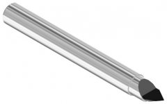
You indicated "etch" but if it's removed my machining it's called engraving. They are available in sizes from very small to large, but basicaly the depth of the toll controls the width of the engraved line.
However, it got me thinking about etching which is a process where a "scratched" line in a plate (that has been protected by a dried resin like varnish) is eroded by acid. The etchings are duplicated by inking the plates and pressing paper onto the surface thus transferring the image. This same process could be applied to a face plate. I don't know if a lacquer paint would be the right stuff or an enamel paint for the "grooves" whatever the process would be. I'm pretty sure you can put enamel over lacquer almost immediatelyand you can't put lacquer over enamel for at least a couple weeks. Anyway, could produce some very artistic results...
Making the "letters"... You could do it in Autocad, save as a DXF and then feed it a program like Cadkey, Gibbs, Bobcad (affordable) or Surfcam (there are dozens) for "post processing". That's turning the data into "G-code", i.e., instructions that move table in X, Y, and Z axis.... an example.
>>>
G1X0.4094Z-0.0288F0.012
G1X0.4882Z0.05F0.012
G0X0.4882Z0.508
G0X0.6154Z0.4766
G0X0.6154Z-1.387
G1X0.6154Z-1.387F0.012
G1X0.5278Z-1.5328F0.012
G1X0.5278Z-2.5578F0.012
G1X0.6066Z-2.479F0.012
G0X0.6066Z-1.5328
G0X0.6066Z-1.5328
G1X0.5278Z-1.5328F0.012
G1X0.3704Z-1.827F0.012
G1X0.3704Z-2.2596F0.012
...
Attachments
Ok, so what I do is:
- Make the drawing in AutoCAD or another CAD program
- Export it in the format the guys who own the CNC machine tell me to
- Let them do the rest
Right 😉?
- Make the drawing in AutoCAD or another CAD program
- Export it in the format the guys who own the CNC machine tell me to
- Let them do the rest
Right 😉?
Also check on laser engraving... might be cheaper ~ 10 seconds machine time vs. 45 minutes. Same output required.
chipco3434 said:Also check on laser engraving... might be cheaper ~ 10 seconds machine time vs. 45 minutes. Same output required.
Hm, well, I plan to get it done in a school, so I don't think they'll charge me much. If I'm lucky I might even use the CNC machine for free. I don't think schools have laser engraving stuff and I fear that getting it done by a company is pretty expensive. Or am I wrong?
Btw, does anybody know a good free CAD program?
If they have CNC machines, then they will have CADCAM. I am not aware that there are any free ones out there. Bobcad has a demo but I don't think you can save the output. Although there is a government site that has uncompiled source code for ISO G... then you could take DIY to a whole new level.
Chipco...
"I have a great place to buy nice solid carbide Eastern Euro endmills, cheap."
Do you sell these (that's what I was thinking), or are you talking about being near a good source?
As to inlaying color onto engraved lettering...
The glassy looking (and very hard) stuff they use in jewelry, pins, etc. is actually a powder that is heated. Available at craft stores. Cut nice deep letters, and you have a permanent and pro looking job.
E
glassy looking (and very hard) stuff they use in jewelry
it's called cloisonne... I could make a VERY COOL CASE COVER!
Between etchings and cloisonne I'm keeping in touch with my "feminine side".
Back to the tough guy talk...
We have a nice place in town that does a lot of close out lots... I don't sell them. You see different stuff. For example, I was there yesterday picking up a goofy tap and they had some carbide cone dremmel burrs for $2.50. At that price it's much cheaper than the hardware. So they have stuff like ball nose, and goofy metric stuff that nobody really wants to multiply by .03937. Good quality, odd sizes.
as to etching...
I once had a 1911 hardballer that had acid etched slide. The detail was crisp, and the contrast was just enough to make for a very classy look.
I checked into the process (this was a long time ago), and found it to be a bit pricey for a one-off... But, a guy might be able to do enough stereo stuff to justify it.
If you look into this option, please keep us informed.
Chipco, that sounds perfect. I could send you a list of collet sizes and types, and some $ for a petty cash fund, and just let the fates and your expertise fill in my collection.
I can think of nothing that would be more helpful around here (well, nothing a -guy- could do...😀 ), but what could I do to return the favor?
E
BTW, Chipco...
The only thing I can think of that might be scarier than seeing your "feminine side", would be watching you order 6 beers with one hand...
A friend and I were contemplating your statement that you could achieve this, and the only way he could see arranging this involves a protruberance that is not normally used to grasp...
E (ric)
- Status
- Not open for further replies.
- Home
- General Interest
- Everything Else
- Cutting, drilling, mounting etc. for the absolute beginner