Hi Gerrit,
The responses in Post#40, show distinct differences.
Earlier I had suggested putting a resistor in series with the NAD to imitate the triode output impedance. However doing this will still not prevent output current phase reversal due to loudspeaker system generated back-EMF.
I first thought about this problem as far back as the 1970's when I found that no SS class-AB amplifier could come close to a tube amplifier or the JLH class-A for relaxed listening, and I reasoned that connecting a fixed resistor across the output terminals of a class-AB amplier in parallel with a loudspeaker load, would do much to reduce output current phase reversal.
Of course this resistor would become hot, and sap away output - but - it did improve reproduction - whilst - at the same time degrading the measured THD.
How ridiculous was that ?
The amplifier was distorting more but sounding better !!!
Could I suggest you run through the Post#40 examinations again with a resistor chosen to match the triode amplifier's output impedance connected in series with the driver, plus another resistor connected directly across the output terminals, say of value equal to the new measured series loudspeaker circuit resistance, in order to see if the NAD can do better than the triode when its load is predominantly resistive ?
If it can be made to measure the same, then it might be made to sound the same too !
Cheers ........ Graham.
I have not read everything in this thread, so I might write something that has already been written. Anyway, the amount of distortion that a loudspeaker driver produces depends on the frequency and the driving impedance. For certain frequencies the driving impedance should be large in order to minimise the distortion, for other frequencies it should be zero or even negative. Which driving impedance that is the best depends on which type of distortion that dominates at the frequency in question.
For example, at high frequencies, the voice coil inductance dominates the driver impedance. Since this inductance is non-linear, it contributes greatly to the driver distortion. Using constant-current drive effectively connects an infinite impedance in series with the voice coil inductance, and this practically eliminates the distortion contribution from the voice coil.
OTOH, at low frequencies the non-linearity of Cms plays a role. These non-linearities can be eliminated if the driver acts as a velocity generator. This happens if the amplifier has an output resistance equal to -Re. Ståhl's ACE method did something similar to this. He expressed it in terms of adding extra virtual stiffness from the electrical side, and given that this extra stiffness dominated, the effects of th non-linarities in Cms was reduced.
So, the optimal driving impedance varies with frequency. And one must not forget that the driving impedance affects the frequency response, this also has to be dealt with. This is complicated, but doable.
PS. The above is actually an argument against using active crossover filters at highish frequencies. The output impedance of passive filters might help in reducing the distortion of the drivers if used correctly. The difference can be significant.
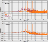
Multi-tone distortion
To see if there is any difference between the voltage and current distortion I constructed a multi-tone signal with the following frequencies: 40Hz, 55Hz, 70Hz, 90Hz, 421Hz and 645Hz. Impedance and phase are all over the place for this set, 645Hz is the only one where the phase angle for both voltage and current is near zero.
Attached is the spectrum for this multi-tone for both amps. The parameters were: FFT size 1536000, SR 96KHz, Rife-Vincent 2 window.
If we look at the voltage spectrum we see that the SET amp performs much worse, there are lots of IM products visible in the spectrum. The environment noise coming from the speaker acting as a microphone is also clearly visible.
The current spectrum shows a completely different picture, the big difference between the amps has disappeared. We would have to look at the details to see which amp has the lowest distortion.
A detailed analysis will take some time but here are some number to get a sense of what kind of distortion levels we're talking about.
Reference 40Hz:
Si V -27.075dBV
NAD V -26.452dBV
Si I -44.943dBA
NAD I -44.372dBA
These are the numbers for the highest peaks in the spectrum relative to the 40Hz reference:
Si V 20.000Hz -66dB (NAD -102dB)
Si I 25.000Hz -64dB (NAD -65dB)
NAD V 17.701KHz -63dB (Si -95dB)
NAD I 48.938Hz -57dB (Si -77dB)
I'm not quite sure what to make of the 48.938Hz peak in case of the NAD, it could be the mains but there is also a peak at 50Hz:
NAD I -58dB
Si I -70dB
Stay tuned, more to follow.
Attachments
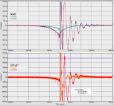
Cross-correlation revisited, feedback schmeedback?
In post #2 the cross-correlation is shown for a very small period of time. The vertical scale is 1, the maximum for the cross-correlation. What if we were to zoom in vertically and look at the 'time distortion'? By this I mean using the same approach as for evaluating harmonic distortion.
The maximum value for the cross-correlation is 1, this makes the interpretation very simple: The 10% distortion point is reached when the plot goes below 0.1, 10m is equivalent to 1% distortion and 1m is equivalent to 0.1% distortion.
The results for both amps are listed below, the value between brackets shows the cross-correlation at that point in time.
10%
NAD 83µs(86m)
SiTuIT 68µs(58m)
1%
NAD 1.375ms(-9.36m)
SiTuIT 1.031ms(-9.94m)
0.1%
NAD 39.719ms(-1.000m)
SiTuIT 36.896ms(-0.989m)
The attachment shows the plot for voltage and current for both amps. The vertical scale is just under 1m (0.1%), the horizontal scale covers 500ms !
As for the 35Hz resonance, all I can think of is that it is half of the main system resonance (70Hz).
The following experiments are indicated:
1. Stuff the Replikon with pilllows to see if this changes the response
2. Repeat the measurement for the NAD with the suggestions Graham made earlier.
Attachments
Hi Gerrit,
I really do not know what to make of these traces.
Could a resonance at 35Hz be due to additional air mass loading acting upon driver resonance ?
Cheers ...... Graham.
I really do not know what to make of these traces.
Could a resonance at 35Hz be due to additional air mass loading acting upon driver resonance ?
Cheers ...... Graham.
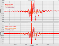
Damping factor, schlemping factor
Hi Graham,
The 35Hz resonant decay must be the result of the driver/enclosure combination.
Stuffing the Replikon with a pillow lowers the frequency of the resonant decay to 30Hz and reduces the amplitude significantly.
I also measured the amps with a Fostex FE208S driver (F) and a 8"Audax driver (A) in free air.
Here are the numbers:
10%
NAD A 125µs(90m)
NAD F 104µs(60m)
Si A 104µs(83m)
Si F 83µs(77m)
1%
NAD A 1.854ms(-9.86m)
NAD F 1.812ms(-9.86m)
Si A 1.500ms(-9.80m)
Si F 1.063ms(-9.93m)
0.1%
NAD A 33.333ms(-0.937m)
NAD F 13.906ms(0.965m)
Si A 21.531ms(-0.997m)
Si F 7.844ms(0.897m)
There's only one conclusion: The tube amp provides better damping.
The attachment shows what happens if an 8ohm series resistor is inserted between the NAD and the Replikon. We see a reduction of the voltage damping, but an increase in the current damping. The current plot for the SET amp is provided as a reference.
Why does it look so different from the plot in the previous post? I forgot to set the digital EQ to bypass ! The signal before t=0 and the other differences are the result the EQ in action. Another can of worms has been opened, sigh.
So far these measurements show that the 'damping factor' as calculated by dividing the number 8 by the output impedance of the amplifier is a misnomer. It should be called 'damping reduction factor'.
Attachments
Hi Gerrit,
So the series resistance does give the NAD a similar current damping characteristic to the triode (which has its own natural internal anode resistance) !
It damps some of the energy which NFB ensured became trapped within the loudspeaker system, but also reduces the storage of those energies in the first place; energies which cannot then fail but to dissipate at (natural) frequencies in series with cabinet, voice coil, and cone impedances other than the impedance dip frequencies at which they originally became stored !
The voltage damping between both amplifiers still does not match, and this suggests to me that the resistor needs to be paralleled with an impedance network which additionally approximates transformer core and winding losses, plus capacitance induced losses arising between the triode electrodes.
Then with such a parallel connected network in series with the NAD, it should indeed 'sound' the same as the triode, this bringing us back to loudspeakers sounding 'best' when driven by an optimum source impedance, this varying with both driver and frequency too, and maybe even being frequency band adjustable via controls on a SS feedback amplifier.
Taking this reasoning forwards - if a series impedance matching network between LS and NAD does match tube performance, then any tube amplifier can be more simply, more efficiently and less expensively replaced by a network plus quality SS NFB amplifier which already provides lower waveform distortion than the tubes can !
This would be the inverse of a parallel network connected across the output terminals of a current source amplifier, which Nelson Pass has already untilised as a valid arrangement.
Controversial or what !
With controllable euphonics too !
Cheers ......... Graham.
Re: Damping factor, schlemping factor
Hi,
I do not know how you have come to this conclusion.
Looking at the amplifier and speaker as a system a low damping
factor increases the Qts (open air) or Qtc (in box) of a bass driver.
http://www.mhsoft.nl/spk_calc.asp#newqts
High values of damping factor are meaningless, low certainly not.
A variable output impedance amplifier http://sound.westhost.com/project56.htm
allows you to vary speaker damping (Q) at will. Low DF = High Q.
🙂/sreten.
Gerrit Boers said:
So far these measurements show that the 'damping factor' as
calculated by dividing the number 8 by the output impedance of the
amplifier is a misnomer. It should be called 'damping reduction factor'.
Hi,
I do not know how you have come to this conclusion.
Looking at the amplifier and speaker as a system a low damping
factor increases the Qts (open air) or Qtc (in box) of a bass driver.
http://www.mhsoft.nl/spk_calc.asp#newqts
High values of damping factor are meaningless, low certainly not.
A variable output impedance amplifier http://sound.westhost.com/project56.htm
allows you to vary speaker damping (Q) at will. Low DF = High Q.
🙂/sreten.
This in fact I have done (partly) a while back, with a chipamp driving a big backloaded horn, fitted with a Lowther driver. The amp was loaded down with a resistor devider to have it play at reasonable levels, and see a benign load, while the driver saw a higher impedance source. I didn't try with reactive networks though, this is a good idea indeed.Graham Maynard said:The voltage damping between both amplifiers still does not match, and this suggests to me that the resistor needs to be paralleled with an impedance network which additionally approximates transformer core and winding losses, plus capacitance induced losses arising between the triode electrodes.
Then with such a parallel connected network in series with the NAD, it should indeed 'sound' the same as the triode, this bringing us back to loudspeakers sounding 'best' when driven by an optimum source impedance, this varying with both driver and frequency too, and maybe even being frequency band adjustable via controls on a SS feedback amplifier.
Taking this reasoning forwards - if a series impedance matching network between LS and NAD does match tube performance, then any tube amplifier can be more simply, more efficiently and less expensively replaced by a network plus quality SS NFB amplifier which already provides lower waveform distortion than the tubes can !
With the network (no matter what kind) it still might not sound the same, I can only suspect nonlinear distortion with a tube amp, especially when driving reactive loads, distorting the load line to an ellipse which then hits regions of higher nonlinearity.
- Klaus
Hi,
Of course it does, but an amplifier is not a resistor. The low impedance is the result of the negative feedback and it works for damping the voltage response. This is clearly visible in the graphs, you can see the back EMF with the higher output impedance. What is also visible is that this back EMF dampens the current response, take it away with feedback and you'll loose damping. There is just no other way to interpret these observations.
Look at the numbers in the previous posts, the SET beats the NAD for every single point.
I can reproduce these results at will and they are not even level dependent.
Looking at the amplifier and speaker as a system a low damping
factor increases the Qts (open air) or Qtc (in box) of a bass driver
Of course it does, but an amplifier is not a resistor. The low impedance is the result of the negative feedback and it works for damping the voltage response. This is clearly visible in the graphs, you can see the back EMF with the higher output impedance. What is also visible is that this back EMF dampens the current response, take it away with feedback and you'll loose damping. There is just no other way to interpret these observations.
Look at the numbers in the previous posts, the SET beats the NAD for every single point.
I can reproduce these results at will and they are not even level dependent.
Great discussion!
The discussion about damping effectiveness vs output impedance takes me back to a lunch discussion a few years ago with a audio friend who is also a RF support specialist where I work. During the discussion we basically came to think that the most effective damping will be when the output impedance of the amplifier is equal to the impedance of the speaker. The question remains "what impedance" as the speaker's impedance is all over the map. As usual the optimum ratio of output impedance is a selection of compromises that will need to be selected for each situation.
This is based on the idea of maximum power transfer occurs in systems where the source impedance matches the load impedance. When the speaker is creating back EMF the fastest way to damp the motion is to pull the power out of the speaker and dissipate it as heat. If the amplifier has very low output impedance no back EMF power is dissipated in the amplifier, only in the resistance of the voice coil. If the amplifier has higher output impedance power will be dissipated in both the voice coil and amplifier and should damp out quicker.
Boys, boys... 😀
We will have to define what "optimal" means here. I can see at least four interpretations in this thread so far:
Which impedance results in
1. ...the lowest distortion?
2. ...the best frequency response?
3. ...the most efficient use of power?
4. ...the neatest look of the voltage/current output from the amplifier?
Number 1 and 2 are IMO the most interesting in normal hifi.
Which impedance results in
1. ...the lowest distortion?
2. ...the best frequency response?
3. ...the most efficient use of power?
4. ...the neatest look of the voltage/current output from the amplifier?
1. You're talking about distortion in the frequency domain, I'm interested in distortion in the time domain. If we look at the multi-tone distortion in the frequency domain there is not much difference between the two amps, the magnitude of the frequency domain distortion is in the order of 0.1% for both amps.
2. Would that be the 'neatest look' of the in-room response?
3. Completely uninteresting.
4. Voltage is irrelevant, current drives the loudspeaker. F=BlI, there's no V in this equation.
The attachment contains another correlation measurement. This time I measured the response on one channel (pseudo-random noise excitation) while playing the multi-tone signal from the frequency domain distortion on the other channel. This should provide some insight into 'acoustic crosstalk'. Pay attention to the vertical scale, 25m is equivalent to 2.5% time domain distortion. Again, the SET beats the NAD.
Attachments

Hi Svante,
Your interpretations make my smile, for whilst Gerrit has objectively visualised significant differences between tube and SS NFB amplifiers, it will, as here, always be 'listeners' and 'mature audio students' who guide the 'measurers' regarding investigation of the abberations which are most significant in relation to quality reproduction.
Gerrit being both listener and measurer.
The lowest audible loudspeaker distortion would actually be from electrically pre-distorted waveforms (specific networks, digital processing or adjustable output impedance designs) which partly compensate for a driver's transduction characteristics. Therefore the 'look' of the waveforms necessary for minimum reproduction distortion (as with motional feedback too) would be quite different not only to what we hear, but to the original signal waveform as well !
Also, a 'best frequency response' cannot provide best listening if coherence has gone out of the window due to frequency selective group delays arising between source and ear. Like THD a frequency response is easy to measure, as often reported in magazine reviews of commercial loudspeakers, and yet we repeatedly see similarly 'flat' frequency responses accompanying different comments and recommendations.
Another story which made me smile;-
http://gedlee.com/downloads/Comments on howard.pdf
From Earl Geddes website / other distortion thread here at diyAudio.
Cheers ......... Graham.
Gerrit Boers said:Hi,
Of course it does, but an amplifier is not a resistor. The low impedance is the result of the negative feedback and it works for damping the voltage response. This is clearly visible in the graphs, you can see the back EMF with the higher output impedance. What is also visible is that this back EMF dampens the current response, take it away with feedback and you'll loose damping.
There is just no other way to interpret these observations.
Look at the numbers in the previous posts, the SET beats the NAD for every single point.
I can reproduce these results at will and they are not even level dependent.
Hi,
Yes there is. A driver is current controlled. Any reduction in current
via output resistance reduces the control of the driver and leads
to a lowering of Qes, effectively your making the magnet smaller
or reducing the number of turns. All your saying is the SET has
less damping / more output impedance than the NAD. So what ?
🙂/sreten.
All your saying is the SET has
less damping / more output impedance than the NAD. So what ?
Where did you get that idea? I'm saying that the SET has MORE damping, not less, and I have results to back up that statement.
The formula for Qes contains Re, R for resistive. The output impedance of an amplifier is not purely resistive, you cannot just add this value to Re and calculate Qes.
Gerrit Boers said:
Where did you get that idea? I'm saying that the SET has MORE
damping, not less, and I have results to back up that statement.
The formula for Qes contains Re, R for resistive. The output impedance of an amplifier
is not purely resistive, you cannot just add this value to Re and calculate Qes.
Hi,
Your definition of MORE damping is not logical unless you
can show that the actual driver behaviour is more damped.
As for your latter statement it hardly matters if it miniscule anyway.
If you choose to build an amplifier with output resistance it is
effectively resistive at sensible frequencies. You can also make the
output impedance complex if you choose, "Stahl ACE bass principle".
🙂/sreten.
Gerrit Boers said:
1. You're talking about distortion in the frequency domain, I'm interested in distortion in the time domain. If we look at the multi-tone distortion in the frequency domain there is not much difference between the two amps, the magnitude of the frequency domain distortion is in the order of 0.1% for both amps.
Why would time domain distortion be interesting? Sorry to put it so blunt, but actually I think time domain analysis rarely adds anything useful.
I was talking about distortion in the loudspeaker. As I said in a previous post, current drive is good for some frequencies, voltage drive, or even negative output impedance is better for others.
Gerrit Boers said:
2. Would that be the 'neatest look' of the in-room response?
Wow. This is a big discussion, but I think it is separate from this one... 🙂
Gerrit Boers said:
3. Completely uninteresting.
Agree.
Gerrit Boers said:
4. Voltage is irrelevant, current drives the loudspeaker. F=BlI, there's no V in this equation.
Well... F drives the mechanichal impedance Zm of the driver. F is not the sound. Zm has a peak at fs. The electrical impedance Ze also has a peak at Ze. These two peaks cancel, more or less.
If you want to analyze what makes the sound, you would have to analyze the entirs chain, from voltage (or current) through the motor and the mechanical impedance, through the cone velocity and finally to the sound.
Not including Zm is sort of like leaving out the RIAA filter in a preamp.
Your definition of MORE damping is not logical unless you
can show that the actual driver behaviour is more damped.
That is exactly what these measurements show, the current damping is better with the tube amp. This can be seen in every single correlation measurement I performed.
The measurements were performed on the system as it is actually used, the amp connected to the loudspeaker in the room (the last result even includes the other channel). In medical science this is called an 'in vivo' measurement.
Measuring amps with resistive loads or loudspeakers in anechoic rooms are examples of 'in vitro' measurements, i.e. an idealized laboratory setting.
During my education as a pharmacist the importance of this distinction was illustrated by the story of the iron in the spinach. This myth is the result of chemical analysis of the iron content in spinach. None of this iron actually enters the bloodstream, as far the human body is concerned there is no iron in spinach at all, the body needs Fe2+ ions, spinach contains Fe3+.
The same is happening here, we based all our conclusions about damping on measurements concerning voltage while we should have looked at the current. Voltage does not enter the 'bloodstream' of the driver, current does.
The map is not the land. If there is a discrepancy, the map is wrong.
- Status
- Not open for further replies.
- Home
- Loudspeakers
- Multi-Way
- Current sense measurements on amp/loudspeaker