I can't see a good reason for the 47 uF cap. Just take the feedback between the .22 Ohm resistor and the load, using any resistor with colours you like. The value is not critical, but it has advantages to use the same value as on the input side. Like you did. This will minimize DC offset and might decrease distortion a bit.
Something like this?Two smps will work if they are isolated from mains.
Im675 for "virtual ground" seems like waste of energy and op-amps ... You could instead try using two lm1875 in BTL (bridge) mode - not sure how the current drive would have to be done, however...
Attachments
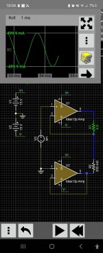
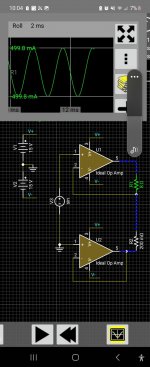
I don't think this will work.Something like this?
The "inverted" amp will massively influence the current-drive-feedback of the upper amp. Probably BTL current drive is not that easy to do.
This is true.I can't see a good reason for the 47 uF cap. Just take the feedback between the .22 Ohm resistor and the load, using any resistor with colours you like. The value is not critical, but it has advantages to use the same value as on the input side. Like you did. This will minimize DC offset and might decrease distortion a bit.
You don't need the 47uF cap.
See this schematic.
But the price to pay is a few mv output offset. In the schematic it is 4mv.
Attachments


As of the encapsulated diode bridge symbols, they do not belong there, worst case square boxes should be drawn with all 4 terminals clearly identified.I think the "rectifier" symbols in picture 1 represent smps (that need to be isolated from primary side!!).
And lm675 can provide up to 4 amps, so in principle should work.
A little "SMPS" label by each won´t hurt, at all 🙂
Ok, the LM675 may have enough current capability, in any case it is an active device passing all the load current through and needlessly dissipating power.
Not sure about the cost, but doubt it´s cheaper than getting the proper CT transformer or using two independent SMPS.
Of course, the trivial solution is using the Single Supply version of the LM1875 amplifier 🙄
The very vast majority of SMPS have a so called floating output.
This is in particular true for Meanwell power supplies.
So in that case you can actually use two SMPS in series, and use the "center tap" as the ground.
This is even explained on Meanwell's website.
There are a few practical caveats to this.
You have to be sure that but start up the same time, otherwise the voltages rails won't be symmetrical.
Some IC's really don't like this at all.
This can be prevented with some circuitry.
Also, a lot of those SMPS go into "energy saving mode" aka hiccup-mode for light loads.
Which can be extremely nasty for audio related stuff.
Splitting the rails can also work, although it can be very fiddly.
Keep in mind that you do half the output voltage, although the current stays the same.
So in the end this results in the need of having to buy one higher power SMPS with an higher voltage.
Or two smaller SMPS with lower voltage and less power (same current)
For example 48V @ 2A = 96W
This will get you 48/2 = ±24V
Or split; 2 x 24V @ 2A = 2 x 48W

I think you're right that the way I posted it will not work well. It's just a driven ground in that ideal case. It's certainly not balanced in the way a voltage out BTL setup is. Even with a symmetrical input signal, the top amp sees the speaker load plus half the sense resistor, while the bottom amp just sees half the sense resistor as load. The way I posted it, the bottom amp sees 0 ohm load (short to ground)I don't think this will work.
The "inverted" amp will massively influence the current-drive-feedback of the upper amp. Probably BTL current drive is not that easy to do.
Already answered in post #25What is the role of 47 mfd in the schematic? Is pure current drive possible with a change here?
Which is the standard way to do it, used by 99.99% of Manufacturers.
You want to save a 25 cent capacitor?
I don't know about standard, but it's a very common way of doing it.Already answered in post #25
Which is the standard way to do it, used by 99.99% of Manufacturers.
You want to save a 25 cent capacitor?
There are many other ways as well.
For the purists, they don't like a cap there sometimes.
How to avoid excessive (openloop?) gain with the speaker not in place across the terminals? Will some sort of Zobel do?
A plain 100-200 ohm resistor in parallel with load will do.
Or turn network into mixed feedback type, allow for a little voltage feedback too, so open load does not turn into full open loop.
Say pure current source gain with normal load is 40X (8 ohm - 0.22 ohm), add a small resistor in series with cap so with no load it shoots up to, say, 400X or tops 800X
Sound will be almost the same, but amp will be safer.
Just for kicks, imagine you nuse NO cap and leave amp unloaded, offset will climb to the roof, output might even hit a rail and stay there.
Not sure amp would be happy.
Hello,
I built a TDA2003 amplifier with current feedback which works nice.
https://www.diyaudio.com/community/...n-to-current-drive.389985/page-7#post-7225986
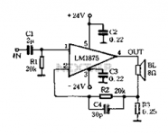
Now I would like to build a stereo amplifier with the LM1875.
In this thread here were several propositions for a schematic to use. Which one should I choose?
Adasons one? Or the one with the 47mfd cap? Or any other?
I built a TDA2003 amplifier with current feedback which works nice.
https://www.diyaudio.com/community/...n-to-current-drive.389985/page-7#post-7225986
Now I would like to build a stereo amplifier with the LM1875.
In this thread here were several propositions for a schematic to use. Which one should I choose?
Adasons one? Or the one with the 47mfd cap? Or any other?
Attachments
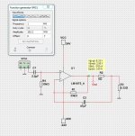
You mean the TDA2003? I posted the thread "Chip amp modification to current drive".What current feedback?!
It was this schematic which seems to work fine.
Attachments
- Home
- Amplifiers
- Chip Amps
- Current feedback application of LM1875