Middelbrook DIT.
Links about this author and his DIT would be helpful.
Thanks in advance.
Hi forr, I find this article covers Middlebrook and DIT well. I hope you will not be put off by the author's position on CFAs. https://www.edn.com/design/analog/4458753/1/In-defense-of-the-current-feedback-amplifier
You will never change forr's mind. You know, if you have a perfect little 3 lead block G = 1 + Rf/Rg always so no matter what's inside they are all the same.
You will never change forr's mind. You know, if you have a perfect little 3 lead block G = 1 + Rf/Rg always so no matter what's inside they are all the same.
Perhaps you're right.
But I can point out the implication of the assertion that there is no current feedback because Rf current doesn't flow into in(-): negative current feedback is a priori impossible!
And I can also highlight that the in (-) CFA transistors' Ebers-Moll transconductive effect is matched by their Early effect. This too has clear implications for the claim that a CFA employs v.f. only and no c.f.
I fully agree with what you write, but that is not what you did with the stand alone LT1001 that came out as a CFA instead of a VFA.My understanding of Middlebrook's DIT is as follows:
A given circuit is normally used with a signal source to excite it. We leave the source connected but set it to zero.
We choose where in the circuit we want to test loop gains: node X. For us, this will be the inverting input.
The first test is to break the loop at X and insert a voltage source to close the break. We can measure the forward and reverse voltages and take the ratio of the latter to the former.
The second test is to connect a ground-referenced current source to point X. We can measure the forward and reverse currents and take the ratio of the latter to the former.
The lesser of the two gains is associated with the more (predominant form of) feedback.
This should have warned you that something was wrong, didn't it ?
Anyhow, this was not what Middebrook had in mind with his DIT test.
See image below,
This is how gentleman should solve their disagreement, I like that.Perhaps I have not convinced you. If so, can you and I dig deep into this article to find the root source of our disagreement?
In a second posting I will take back the importance of assigning an output with the other more complex circuit with LT1001 and current source.
Hans
Attachments
I found this :Hi forr, I find this article covers Middlebrook and DIT well.
http://ecee.colorado.edu/~ecen5807/course_material/papers/eet/Middlebrook_EET.pdf
One never knows.I hope you will not be put off by the author's position on CFAs. https://www.edn.com/design/analog/4458753/1/In-defense-of-the-current-feedback-amplifier
I fully agree with what you write, but that is not what you did with the stand alone LT1001 that came out as a CFA instead of a VFA.
This should have warned you that something was wrong, didn't it ?
Anyhow, this was not what Middebrook had in mind with his DIT test.
See image below,
This is how gentleman should solve their disagreement, I like that.
In a second posting I will take back the importance of assigning an output with the other more complex circuit with LT1001 and current source.
Hans
Hans, you are assuming that I was testing circuit forms that I never intended to test.
Please recall that I can choose to insert the DIT at any point I choose. I chose the points that I intended.
In the case of the first circuit, the circuit I was testing before applying Middlebrook never had any resistors connected to the inverting input - only the current source. To add resistors would have tested a circuit other than what I had intended.
In the case of the second circuit with the 100 ohm resistor, I purposely tested the resistor in combination with the inverting stage. Middlebrook places no restrictions on the point I choose to apply his test, and the location I chose was exactly what I intended.
So perhaps we have another miscommunication after all, which, while unfortunate, is more easily resolved than a disagreement! What do you think?
Tournesol,
This is not an unimportant aspect. The answer would be a resounding no. Transistors have insufficient ability to cope with the wide signal spectrum even at fairly low level amplification and light loads. Most amplifiers exhibit poor bandwidth therefore massive high frequency distortion. Obtaining good high frequency response is a cumbersome balancing act and as far as I can tell, the subject has been entirely left out of the scope of discussion on this website. High frequency response is the main distinguishing quality factor between amplifiers.
I look forward to your postings and meant to respond to a previous one N101N.
There are integrated devices in technology today that have qualities seemingly beyond reproach, particularly in relation to high frequency performance. To a large degree this has to do with drastic reductions in the physical size and dimensions, as most notably in the lengths of internal wiring that integration allows. This integration diminishes the wavelength of frequencies along the length of internal connections and parts, hence drastically raises the frequencies that integrated devices begin failing to function.
Discreet networks require modelling long wires as transmission lines being interfered with by parasitic capacitances often too prolific to even attempt to model at those same frequencies. Without creating transmission lines and ground planes in conjunction with chip transistors and passive components it seems ludicrous to even attempt simulations.
In the past, respectable (in specifications measurable), high quality, high frequency oscillators in the 100MHz region were constructed from transistors and through-hole passive devices, being riddled with compensation devices inside of a half dozen separate mu-metal enclosures and interconnected with critically terminated transmission cables. It is suspected that those advocating the use of discreet transistor parts are also advocating the use of through hole passive parts. Amplifiers constructed of through hole parts, as requiring greater care than an oscillator, are thrown together by comparison.
Bear in mind I have no objections in the slightest to the use of discreet devices or integrated ones. My only benchmark is in relation to its psycho-acoustic impact... as likely to be advanced from my ongoing delusion.
Link ?This is of of course nonsense. Even here there are open-loop amps with 90+dB THD into 1K loads with 250kHz plus BW.
For the moment, the best i can see in power amps for audio is ~10KHz.
May-be it is what you'll call a phantasm, but I will be fully satisfied, on an intellectual point of view, when I will see an amp with a constant feedback ratio, a flat phase curve and a flat (low ) distortion curve all along the audio range (20-20 000).
Free to you to think it is a nonsence. I will never call this way other's preferences, tastes and opinions.
Because we still have a lot to learn about psycho-acoustics or if only for politeness.
Last edited:
So there is no reason to call them otherwise than voltage amplifiers.You will never change forr's mind. You know, if you have a perfect little 3 lead block G = 1 + Rf/Rg always so no matter what's inside they are all the same.
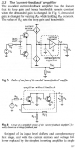
Excerpts from
E.M.Cherry, IEE Proc/-Circuits Devices Syst; Vol 147, No 6, December 2000
"Feedback amplifier configurations""Feedback amplifier configuration" :
IEEE-CDAS_Cherry_Feedback-amplifier-configurations_Dec-2000.pdf - Google Drive
Attachments

Last edited:
So there is no reason to call them otherwise than voltage amplifiers.
Are you going to continue to ignore challenges to your way of thinking in favor of posting yet more unrelated opinions lacking justification from a fellow iconoclast?
but I will be fully satisfied, on an intellectual point of view, when I will see an amp with a constant feedback ratio, a flat phase curve and a flat (low ) distortion curve all along the audio range (20-20 000).
These are all the same thing of course, so you're looking at an ol bw of beyond 20k.
I've met many opamps that satisfy this. I remember building a poweramp with 6 dual AD815's in balanced bridged for 30W/channel. That's an opamp with 20+kHz ol bw. The fact that it also can deliver almost half an amp per opamp is a bonus.
Ohh and BTW it's a CFA 🙂
Ohh and BTW2 I think Scott designed it. Or one of his buddies.
Jan
Attachments
"So there is no reason to call them otherwise than voltage amplifiers."
Absolutely they are voltage amplifiers - no debate about that point. However, if its a CFA voltage amplifier, it uses current feedback.
Absolutely they are voltage amplifiers - no debate about that point. However, if its a CFA voltage amplifier, it uses current feedback.
The CFA sx-Amp has a >60 kHz loop gain -3dB bandwidth - its what I call a 'classic' CFA - so distortion is higher than VFA because the loop gain is lower, but its a very fast, wide BW amplifier.
What I think is quit simply that Middlebrook attempts with his DIT test to discriminate VFA's from CFA's.Please recall that I can choose to insert the DIT at any point I choose. I chose the points that I intended.
In the case of the first circuit, the circuit I was testing before applying Middlebrook never had any resistors connected to the inverting input - only the current source. To add resistors would have tested a circuit other than what I had intended.
In the case of the second circuit with the 100 ohm resistor, I purposely tested the resistor in combination with the inverting stage. Middlebrook places no restrictions on the point I choose to apply his test, and the location I chose was exactly what I intended.
And for that you have to make the cut at the right point.
Of course you are free to make the cut wherever you like, but the outcome seems at least disputable whether it can still be used for separating VFA's from CFA's.
And when a LT1001 comes out as a CFA, it's enough reason to raise the eyebrows, unless you wanted by purpose see what happened when making such a strange connection as if the input impedance was only 100 Ohm.
But that doesn't turn a LT1001 into a CFA to my opinion.
But now to the more complex circuit design that you made with the added current source.
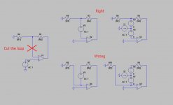
You are right that a cut should always be made right before the minus input and that the voltage and current sources can be inserted at this spot for doing a DIT.
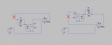
In this very case there are two ways to look at the circuit making a big difference where the cut is made.
One is seeing this current source construction as integral part of the input and the other as seeing the current source as a sort of Rf, where the cut should be made after the current source and thus before the minus input of the LT1001.
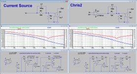
See image below.
In my first Sim, I made the cut directly after the LT1001 as in the left part of the image below. This is what I called "Chris".
By placing the cut after the current source and before the minus input of the LT1001, gave the one that you used. This is the part that I called "Chris2".
So we were doing the same thing, but just cutting at different places.
Now at the same spot, our results are of course identical.
Below at the left is what you did and at the right what I did with "Chris2".
And forget what I said about placing the label "Out" at he right spot, because in the calculation of Ti and Tv, there is no reference to V(out) at all.
Hans
P.S. This same Sim was made in #1733 as one of the two, so the remarks made over there are stil valid.
Attachments
Last edited:
Of course 🙂.These are all the same thing of course, so you're looking at an ol bw of beyond 20k.
A little acrobatic, no ? What about distortion and damping factor ?I've met many opamps that satisfy this. I remember building a poweramp with 6 dual AD815's in balanced bridged for 30W/channel. That's an opamp with 20+kHz ol bw. The fact that it also can deliver almost half an amp per opamp is a bonus.
Anyway, look at the attached: more or less what i said, ~10K , no ?
Of course ;-)Ohh and BTW it's a CFA 🙂
I'm an old AD/PMI addict ;-)Ohh and BTW2 I think Scott designed it. Or one of his buddies.
Attachments
What I think is quit simply that Middlebrook attempts with his DIT test to discriminate VFA's from CFA's.
And for that you have to make the cut at the right point.
Here I must disagree. Middlebrook's test is designed to identify the current and voltage loop gains at specific points in any and all circuits, regardless of their names or topologies. It makes no attempt to identify circuit topologies, if that's what you mean by CFAs vs. VFAs. We can infer topologies from test results, but as I have identified, we do so at great risk.
If you'd like, I can demonstrate through simulation of ICs identified by their manufacturer as CFAs that their recommended circuits for certain gains have a predominance of v.f.
Of course you are free to make the cut wherever you like, but the outcome seems at least disputable whether it can still be used for separating VFA's from CFA's.
If by separating CFAs from VFAs you mean determining circuit topologies, I maintain that it is an unreliable means for doing so, nor was it ever a stated intention of Middlebrook for it to be used as such. And I am not bothered by this - I use it for its analytic capability, and its ability to determine which of the two types of feedback is dominant at a specific point in a particular circuit. These, I believe, are its intended purposes, which it accomplishes quite well.
And when a LT1001 comes out as a CFA, it's enough reason to raise the eyebrows, unless you wanted by purpose see what happened when making such a strange connection as if the input impedance was only 100 Ohm.
But that doesn't turn a LT1001 into a CFA to my opinion.
Please be aware that I never, ever claimed that it did - only that the LT1001 can be employed in a circuit in which c.f. predominantes.
But now to the more complex circuit design that you made with the added current source.
You are right that a cut should always be made right before the minus input...
I never said this. When offering an opinion on the topic, I have always said I can put the cut wherever I want.
...and that the voltage and current sources can be inserted at this spot for doing a DIT.
In this very case there are two ways to look at the circuit making a big difference where the cut is made...
Hans
Yes, good we get the same results. I think that the span of our disagreement is narrowing. Let's see if we can close it further.
Does a test exist which can demonstrate the predominant form of feedback at any point within a closed loop circuit? I think we can both say yes - Middlebrook's DIT. Comments?
Does a test exist which can determine the topology (CFA vs. VFA) of the "gain block" (open loop amplifier) when mated with some sort of "standard" feedback network? I'm willing to be convinced, but I think it would be possible to weasel a way around it.
Does a test exist which can determine the topology of the "gain block" when mated with an arbitrary feedback network? This I doubt. Thoughts?
Middlebrook never intended DIT to determine circuit topology. Comments?
What about distortion and damping factor ?
You can extrapolate from the data sheet as well as I can ;-)
Jan
IMHO your both right. Non of the classic feedback catagories fit ( shunt shunt etc.) ( Need more study and probably some help ) but what i see in a CFA is a 2 stage amp with nested feedback. First stage is a V to I amp with a "current error signal". This I goes thru a I to V converter and then into a voltage buffer which I assume has a voltage error signal. This voltage output is then fedback to the first stage as voltage, current or both depending on the feedback network. Maybe nonsense but after 175 pages of both sides being right and wrong, maybe not. My name for this would be a hybrid opamp, although I doubt HOA would pass marketing.
Last edited:
- Home
- Amplifiers
- Solid State
- Current Feedback Amplifiers, not only a semantic problem?