Irrelevant ?... at least, you admit that the Vbe approach doesn't go again the facts.Originally Posted by forr
let me quote Scott :
A bipolar transistor's Vbe vs Ic relationship is essentially all that matters. A transistor is NOT a current controlled device, the base current is incidental determined by poorly controlled parameters like base width and recombination. The Vbe equation is fundamental physics.
( Current Feedback Amplifiers, not only a semantic problem ? )
Since thirty years, my thinking on linear circuits using bipolar transistors relies on reasons wich place the above Vbe driving current propriety in the first position.
Originally Posted by jan.didden
As usual, out of context. The 'CFA' claim does not claim otherwise; this argument is irrelevant.
Jan
But it is the exact role given to the current to justify the name of CFA which is under scrutiny. And this, whatever has been said or written remains unclear not to say incoherent.
To me, a way to see the CFA topology is to consider that the current circulating in the inverting input is converted to voltage by the load of this inverting input before the real feedback process of voltages substraction which, with bipolar transistors, is undertaken by the Vbe voltage and outputs a current which is exploited by the remaining part of the circuit.
An other way which I prefer is to consider that the CFA inverting input is the output of a voltage follower, its load being a voltage seen through the impedance at the divider point of the feedback network.
Any change in this voltage constitues a change of the load impedance seen by the inverting input. To maintain its output voltage equal to its input voltage, the voltage follower must deliver the adequate quantity of current. With bipolar transistors, the adequation is under the control of the Vbe voltage. It is the Vbe which realizes the real feedback process.
In a differential input, the inverting output contains a buffer between the impedance divider point and the device which receives the input signal and proceeds to the feedback voltages subtraction. This leads to somewhat different properties but the fundamental principle is the same.
Your point of view seems to consider that the input current circulating in the inverting input of a bipolar CFA forces its active devices to be in common-base configuration. I do not agree because if the feedback network is disconnected from the output of the whole circuit, these active devices would behave mostly like emitter followers. I am not sure they can change of configuration according to the presence or the absence of the said connection.
We hear you load and clear.
Not that I disagree with Mr. Wurcer, but who's "we", mind you? I don't recall you being appointed to represent anybody's views, on or off topic. So you may want, in general, to speak for yourself.
has anyone yet noticed I talk about current-mode operation of a circuit and others here talk about feed back (CFB) to a low Z input.
??
How about starting over and describe what is the difference between circuits which are Current Mode and Voltage Mode operation? ..... and then some CMode topologies.
THx-RNMarsh
??
How about starting over and describe what is the difference between circuits which are Current Mode and Voltage Mode operation? ..... and then some CMode topologies.
THx-RNMarsh
Last edited:
has anyone yet noticed I talk about current-mode operation of a circuit and others here talk about feed back (CFB) to a low Z input.
How about you start and explain what you mean by "current-mode operation of a circuit". Inquiring minds want to know.
Which part of your body do you use for tracing currents?
Brain. I see the whole picture and feel how it works.
I don't understand - are talking about the rise in distortion as the input level signal decreases as depicted on the Vout vs distortion plots? Can you put up an example to make your point clearer?
Here you go.
Attachments
Last edited:
Come on folks, some here have invested a lot of time in realizing their ideas and I have seen enough to believe dadod, Bonsai, and ex participants like Ovidu and Glen K have all built exemplary PA's. Why get hung up on what they're called? It might be that it's not literally "current feedback" but I proposed an angle where the concept is not completely bogus especially as a heads up to the average designer. This acrimony serves no purpose except to drive people away. We all sometimes disagree we all sometimes are not totally correct and we all depend on a lot of previous work by many other people.
I have to agree that GK and O built exemplary PA's.
IIRC you said something similar at Andy's site days before GK, O and myself was put in Read Only Mode. A week later the whole place was history.
I think that you forgot Edmond (sorry Waly).
BTW: I get your point and will not post anymore.
Have fun
S
See this post for an explanation of why the curve looks like that Wavebourn
Current Feedback Amplifiers, not only a semantic problem ?
Current Feedback Amplifiers, not only a semantic problem ?
See this post for an explanation of why the curve looks like that Wavebourn
Current Feedback Amplifiers, not only a semantic problem ?
Sorry, it does not work. You already called it exceptionally quiet. Too late.
How about you start and explain what you mean by "current-mode operation of a circuit". Inquiring minds want to know.
... and do it in one sentence, right? ....... OK. --- Here:
Current mode circuits | Vishwam Gupta - Academia.edu
Have to start some where-- might as well be here.
can you design a current mode audio amplifier? Or mostly CMode? CMode quickly moved into using CMOS for increased speed for RF/uwave ---- But we can do it in fet or bipolar for audio/LF.
?
THx-RNMarsh
Last edited:
Sorry, it does not work. You already called it exceptionally quiet. Too late.
??
Here you go.
I suspect that this has nothing to do with feedback.In balanced (PP) circuits there is always some sort of crossover distortion.As the signal grows the part of the crossover region gets proportionally smaller, less distortion.
Feedback to the emitter and input at the base make the base-emitter juction part of the feedback substracting mechanism and the result is influenced by a non-linear element.So i suppose the so called CFB is perhaps better for high frequencies but not against distortion.
Mona
Rising distortion has nothing to do with CFA/VFA. In the case of THD + N it can easily be masked by noise. If you have crossover distortion it affects both more or less the same.
I haven' said it is CFA characteristic, just showed CFA simulation.
Of course it has nothing to do with feedback. Just as I said, I would not use such a device for audio, even it is excellent for DSL applications.
Clarification: I too did not mean any topology that falls under this clarification. I just meant the particular device.
Clarification: I too did not mean any topology that falls under this clarification. I just meant the particular device.
Last edited:
Irrelevant ?... at least, you admit that the Vbe approach doesn't go again the facts.
.
Is that what you are looking for? That I agree to facts? You really are loosing it.
But it is the exact role given to the current to justify the name of CFA which is under scrutiny. And this, whatever has been said or written remains unclear not to say incoherent.
No it does not, except to you.
To me, a way to see the CFA topology is to consider that the current circulating in the inverting input is converted to voltage by the load of this inverting input before the real feedback process of voltages substraction which, with bipolar transistors, is undertaken by the Vbe voltage and outputs a current which is exploited by the remaining part of the circuit.
You are of course free to consider anything the way you want.
An other way which I prefer is to consider that the CFA inverting input is the output of a voltage follower, its load being a voltage seen through the impedance at the divider point of the feedback network.
As I said, your prerogative to consider whgatever you want. Is there a point to this?
Your point of view seems to consider that the input current circulating in the inverting input of a bipolar CFA forces its active devices to be in common-base configuration. I do not agree because if the feedback network is disconnected from the output of the whole circuit, these active devices would behave mostly like emitter followers. I am not sure they can change of configuration according to the presence or the absence of the said connection.
You misread my point of view. Now let me try to read your view. Are you suggesting that a circuit topology is independent of the actual circuit?
Jan
Not that I disagree with Mr. Wurcer, but who's "we", mind you? I don't recall you being appointed to represent anybody's views, on or off topic. So you may want, in general, to speak for yourself.
Waly, this is diyAudio forum, I hope you've noticed that. I will be happy if you could suggest some circuits, improvements suggestion and so on, not just criticized all around. I know you a very knowledgeable much more then me. I am old and forgot most of things I learned at University, you are young and you could point your skill in helping diy community here.
I have a great hope in you, just put some effort.
Damir
Of course it has nothing to do with feedback. Just as I said, I would not use such a device for audio, even it is excellent for DSL applications.
Clarification: I too did not mean any topology that falls under this clarification. I just meant the particular device.
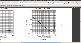
Its 3 ppm at 3V into 600 Ohms. The plots IIRC were primarily low order (2nds and 3rds) and higher orders only manifest at 150 Ohm loads. The distortion vs output is well below the AP SYS272 resolution at levels below 3V RMS output.
You say you would not use it but why?
I suspect that this has nothing to do with feedback.In balanced (PP) circuits there is always some sort of crossover distortion.As the signal grows the part of the crossover region gets proportionally smaller, less distortion.
Feedback to the emitter and input at the base make the base-emitter juction part of the feedback substracting mechanism and the result is influenced by a non-linear element.So i suppose the so called CFB is perhaps better for high frequencies but not against distortion.
Mona
Plenty of PA's that show sub ppm distortion in sim, and low single digit ppm on actual measurements - see some of Dadod's amps for example. So I do not think it is correct to assume CFA's are inferior because of this.
On and OPA, I would expect as the signal level is decreased, you end up in the class region of the opamp - especially so when the load is the more typical 10k or 20k. In any case, very easy to bias the OPS into class A. You get exactly the same distortion profile.
You say you would not use it but why?
Because different solutions satisfy my needs better.
... and do it in one sentence, right? ....... OK. --- Here:
Current mode circuits | Vishwam Gupta - Academia.edu
Have to start some where-- might as well be here.
can you design a current mode audio amplifier? Or mostly CMode? CMode quickly moved into using CMOS for increased speed for RF/uwave ---- But we can do it in fet or bipolar for audio/LF.
?
?
Link requires some sort of authentication. I can't design a damn thing until I know what it is and performance target is specified. And for you it won't be free, anyway.
Mixing in one phrase CMOS, Microwave, RF, audio is... you know what.
- Home
- Amplifiers
- Solid State
- Current Feedback Amplifiers, not only a semantic problem?