You may also use only positive feedback if you want. Barkhausen´s theorem say that for sustaining oscillation in a closed loop device (Electric, electronic, mechanical, hydraulic ot whatever you want to consider), two equations must be satisfied:
1.- Total loop gain ( A * ß ) = 1
2.- Phase angle equal to zero or integer multiple of 360°.
If any of this two aren't satisfied, then no oscillation at all. In the above examples I mentioned, in the bootstrapped stage A * ß is always less than 1 because a follower never reaches gain of 1, then no oscillations can be maintained in the time.
(Note: A is the closed loop gain, ß or beta is the return factor of the amp).
In the past, several computational amplifiers could be done thanks to use of positive voltage or current feedback, as gain of tubes wasn't too high as modern ss devices (Opamps). In the Samuel Seely´s "Electron-Tube Circuits" book there are several examples of what I am trying to explain.
Cordially Osvaldo.
Counter-examples : an amplifier with negative resistance output, in the old days, a Current Positive Feedback Amplifier. Or some error correction amplifiers.You said positive feedback? That makes an oscillator.
Last edited:
Edit: this is the article I meant: https://linearaudio.nl/sites/linearaudio.net/files/miller combined fb electronics march 1950.pdf . Fig 3 is of interest.
Jan
I took him into account googling for his patent US 2652458 several months ago, but it is the same author and schematic as you are referring above.
In any case, thanks for the pdf data.
I'm quite disappointed how unserious and ill prepared you were in trying to come with a "Prove".
Hans,
I don't know what's happening to you, but IMHO you should go back to a constructive attitude and take the time to have another look on the scheme.
Moo a Koo is now sending emails to my commercial business account criticizing my use of ‘so called CFA’ (his words) and some other stuff.
The anti- CFA brigade are nuts.
The anti- CFA brigade are nuts.
The guy needs serious help. Serious.
Jan
Agree 100%. Unfortunately, he doesn't know about it.
Cheers,
Valery
Edit: this is the article I meant: https://linearaudio.nl/sites/linearaudio.net/files/miller combined fb electronics march 1950.pdf . Fig 3 is of interest.
Jan
I downloaded and printed the article. A read in the last weekend reveals something different to what I was saying. Also in the us patent above mentioned, Mr Miller talk us about positive voltage feedback around one stage, while I was writing about positive current feedback, in my project, involving the entire amplifier. They are different thinks. And effectively, I could note using a cheap re-coned 8" speaker with no baffle, how increasing slowly the amount of positive current from the zero to a say, 40% of the preset that I let there with this intention; bass notes were accentuated and resonance apparently disappeared, clearly both effects are linked to the sudden drop of the output impedance of the amplifier.
Moving the preset to more than 60% with such a load, clearly the amp starts to oscillate, not without the load. This is because current feedback makes the load to participate in the feedback loop where voltage feedback doesn't.
Yes different things, agreed.
In the case of positive current feedback like in your case, you are actually getting negative output impedance for the amp. That is, when load current rises, also output voltage rises! This is the cause of the phenomena you describe. Maybe you saw large excursions of the cone even before the onset of oscillations?
Like you say, it is sensitive to adjustments and very easy to overdo it. In systems where it is used, it often is combined with 'normal' voltage nfb with an adjustment to set the balance between the two. Also sometimes limiting the pos fb to a specific frequency range.
You opened a big can of worms!
Jan
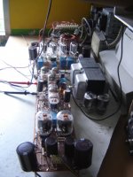
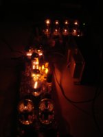
OK, look at this. My project is to use all-compactron tubes with multiple units, and the final stage are two 6JN6 in series push-pull using an autotransformer to match the load (2KΩ to 6Ω). By the moment the device is very unmaturated, and many weeks it took to me to arrive to a decent amplifier, after trying several configurations. It will have its own thread when more or less finished. I may assure that the project is very complex and involve 8 tubes (4 for the first stage, 2 for the second ones plus 2 output pentodes) of the said type, for each stereo channel. The power supply are 4 * 6AX3, compactron damper tubes and I added a mechanism to perfectly compensate the DC balance respect to ground using an AC + DC NFB plus a AC PCF, using split rails of ±270Vl, and included 3 neon lamps as voltage references for two current sink (Constant current devices) in both driver and input stage. The amp is DC coupled and more or less stable by the moment.
In the project influenced no less than 28 sources (readings) including books, patents, articles from magazines and papers. But, please, wait a bit for finishing the design stage, but with outside temperature of +32C and feeling like 38, I don't want to have heaters heated, ha ha ha...
Look this pics as an advance.
Attachments
Gents, can I give a new twist to this discussion?
I got some material from Michael Steffes, erstwhile opamp designer at BurrBrown.
Look at the data sheets for the OPA847, or the Renesas ISL55210. VFAs, 4GHz BW, 0.85V/RtHz noise, 5600V/uS slew rate, etc.
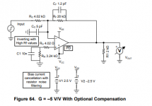
See also the OPA838 data sheet, in particular fig 64, a compensation technique I haven't seen in the audio scene yet.
Do we still see a need for a CFA topology, or has it's time in the spotlight passed?
Jan
I got some material from Michael Steffes, erstwhile opamp designer at BurrBrown.
Look at the data sheets for the OPA847, or the Renesas ISL55210. VFAs, 4GHz BW, 0.85V/RtHz noise, 5600V/uS slew rate, etc.
See also the OPA838 data sheet, in particular fig 64, a compensation technique I haven't seen in the audio scene yet.
Do we still see a need for a CFA topology, or has it's time in the spotlight passed?
Jan
Attachments
Last edited:
Gents, can I give a new twist to this discussion?
I got some material from Michael Steffes, erstwhile opamp designer at BurrBrown.
Look at the data sheets for the OPA847, or the Renesas ISL55210. VFAs, 4GHz BW, 0.85V/RtHz noise, 5600V/uS slew rate, etc.
See also the OPA838 data sheet, in particular fig 64, a compensation technique I haven't seen in the audio scene yet.
Do we still see a need for a CFA topology, or has it's time in the spotlight passed?
Jan
Jan,
Impressive, OPA's with 4GHz BW, wow !
The compensation for the OPA838 to cancel the input capacitance thereby flattening the FR is a well known technique .
A single cap on Rf is normally enough, but when the value becomes too small to handle such as with very high speed amps, an extra cap on the input will bring it back to manageable values.
The 10nF cap to reduce noise, while keeping the DC offset low, could also be used for Audio designs when input current is contributing significantly to the output noise, but in most Audio cases this will probably not be very relevant.
Hans
Yes, the Cf probably defaults to the parasitic. And 100kHz OL BW, the religious high OL BW crowd should get a hard-on from this for the rest of their lives ;-)
Hans what do you think, putting Cg across Rg instead of to gnd, would that not be better?
Jan
Sorry for the ignorance, this threat is too long to catch up as newbie.
Did anyone consider, that the distortion problem with constant voltage amps is not the low output impedance. It may be the high feedback that does not involve the whole speaker but only the load on the amp?
I have speaker with moving coil pickup on the cone, which is included in the feedback of the current amplifier, and it does not have distortion issue because it involves all components, rather than a part only.
Just throwing assumptions!
cheers
Josh
Josh, this thread is not about traditional current feedback, where you sense the load current and use that as feedback signal.
It is about a type of opamp where the inv input is an emitter rather than a base. And if you now think, what's all the fuss about, you are right! ;-)
But that is the background here.
Jan
It is about a type of opamp where the inv input is an emitter rather than a base. And if you now think, what's all the fuss about, you are right! ;-)
But that is the background here.
Jan
- Home
- Amplifiers
- Solid State
- Current Feedback Amplifiers, not only a semantic problem?