The active device current is the opposite of the difference between output and ground feedback network signal current.
It is conform with a strict application of Kirchhoff law on node In- where Rf, Rg and active device are connected.
The "difference between" has no inherent polarity. But I agree that in a CFA, the network ground current magnitude is equal to the sum of the magnitudes of the output and In- currents. This establishes a simple linear relationship between the latter two signals.
What I understand of the MDIT is that if feedback network impedance is greater than In- open loop impedance, current loop gain is lower than voltage loop gain. Consequently, if feedback network impedance is lower than open loop In- impedance, voltage loop gain is lower than current loop gain.
(feedback network impedance as it appears to the inverting input) Yes, to a very good approximation in practical situations.
So the classification given by the test depends on external components and not only to its topology...
MDIT does not deal in classifications. It does not identify topologies. It measures loop gains.
This is obtained with CFA in inverter mode, which is not the most common use of CFA, where the In- impedance is at its lowest value.
To be a CFA in inverter mode, there would have to be a signal applied to what is in this circuit the ground terminal of the feedback network, which there is not. In MDIT, there is neither the standard inverting nor the standard non-inverting mode operation. Signals which would be applied in such situations are set to zero. Instead, signals are applied inside the loop, where they would never be in standard operation.
If we run the same test with a signal at In+, voltage or current signals, results are always the same : voltage loop gain is always lower than current loop gain.
It is not the same test if you apply a signal to In+. In such a case, you are not measuring loop gains.
My conclusion...
... is, I fear, not justified because of the reasons I mentioned above.
As far as I know, "unprovable" applies to all theories.
I’m glad you have so much self reflection.
Hans
It calculates loop gain. And the result is used to classify the DUT in the VFA or CFA category, depending on the predominant feedback mode.MDIT does not deal in classifications. It does not identify topologies. It measures loop gains.
To be a CFA in inverter mode, there would have to be a signal applied to what is in this circuit the ground terminal of the feedback network, which there is not. In MDIT, there is neither the standard inverting nor the standard non-inverting mode operation. Signals which would be applied in such situations are set to zero. Instead, signals are applied inside the loop, where they would never be in standard operation.
Signal is applied on inverting input, non inverting input is grounded, DUT is in inverting mode. I agree this is a non standard inverting mode.
I confirm it is not the same simulation scheme.It is not the same test if you apply a signal to In+. In such a case, you are not measuring loop gains.
The simulation shows that when the DUT is in "standard" working conditions, as the In- impedance is increased by the feedback, the ratio between fraction of injected voltage signal present at Rg and Rf common node and the fraction of injected voltage signal present at In- is far lower than the ratio between fraction of injected current signal flowing in Rg//Rf and the fraction of injected current signal in In- . This indicate that predominant feedback mode is voltage.
I’m glad you have so much self reflection.
Hans
Hans,
It would be better if I knew why, but I'm happy to see you glad.
It calculates loop gain. And the result is used to classify the DUT in the VFA or CFA category, depending on the predominant feedback mode.
Used by whom ??
Hans
Used by whom ??
Hans
Not sure to remember their name.
But I'm pretty sure one of them wrote something like that :
""By doing that, three transimpedance T curves can be obtained.
Ti by means of current injection, Tv with voltage injection and the loop gain T.
When the FR plot of Ti is close to T's plot, it is a CFA.
When the FR plot of Tv is close to T it is a VFA.
When Ti and Tv are equal, we have 50% CFA and 50% VFA.""
Herve,
Why don’t you use the other test that I designed to really classify a CFA or a VFA and please show with a real world example where it doesn’t do its job propely.
If needed and if possible, this test could even be improved.
That would be a whole lot more constructive.
Hans
Why don’t you use the other test that I designed to really classify a CFA or a VFA and please show with a real world example where it doesn’t do its job propely.
If needed and if possible, this test could even be improved.
That would be a whole lot more constructive.
Hans
It calculates loop gain.
Agreed.
And the result is used to classify the DUT in the VFA or CFA category, depending on the predominant feedback mode.
Here I would disagree. Yes, the parameter with the lesser loop gain is associated with the predominant feedback mode. But the industry associates the terms CFA and VFA with circuit topologies, because the predominant feedback mode of a specific complete circuit can vary with the feedback network employed by the user. For some ICs which are identified by their manufacturers as CFAs, at certain closed loop gains it is quite possible to find recommendations of feedback networks with lower impedances than that of In-. Manufacturers do not sell and specify complete circuits with specific feedback networks; they sell gain blocks, which they distinguish as VFAs or CFAs. The latter name they justify because of the ever-present relationship between input and output stage currents, not because of the predominant form of feedback, which is affected by the user's choice of feedback network.
Signal is applied on inverting input, non inverting input is grounded, DUT is in inverting mode. I agree this is a non standard inverting mode.
Are you talking about setting In+ to zero and inserting a voltage source between ground and Rg? I would consider this to be the standard inverting mode, which I agree is rarely used with what the industry calls CFAs.
I confirm it is not the same simulation scheme.
The simulation shows that when the DUT is in "standard" working conditions, as the In- impedance is increased by the feedback, the ratio between fraction of injected voltage signal present at Rg and Rf common node and the fraction of injected voltage signal present at In- is far lower than the ratio between fraction of injected current signal flowing in Rg//Rf and the fraction of injected current signal in In- . This indicate that predominant feedback mode is voltage.
Suppose I connected ground-referenced voltage signal sources Vp and Vm to In+ and to the side of Rg which would otherwise be grounded. I set the outputs of these sources to zero - they are effectively short circuits. I also connect the two sources I need to run MDIT, which I then execute. I obtain current and voltage loop gains and determine the predominant form of feedback.
Next, I zero the outputs of the MDIT test signals (returning the circuit to "normal" operation), and allow Vp and/or Vm to take on non-zero values. If this actually caused the loop gains and feedbacks to change from what MDIT gave us, then MDIT would be totally useless - its results would be irrelevant to how the circuit is actually used. Why then would anyone pay attention to MDIT?
There is a reason that MDIT exists, and that to determine loop gains, it requires the In+ voltage to be zero and Rg to be grounded.
Herve,
Why don’t you use the other test that I designed to really classify a CFA or a VFA and please show with a real world example where it doesn’t do its job propely.
If needed and if possible, this test could even be improved.
That would be a whole lot more constructive.
Hans
Hans,
My actual need is not to classify CFA and VFA. What I try to do is demonstrating that in almost "standard" use condition the predominant feedback mode in CFA is voltage.
To come back to your test, it seems it has difficulties to identify which input of the DUT is of low impedance.
As an example, you can see your test applied on a simple folded cascoded fet input amplifier (non optimized) we often use as charge or current amplifier where the negative input is high Z and the normally grounded non inverting input is the source of the fet.
I don't think we can classify it as a CFA as the fet current don't flow in the feedback network, but your test does it.
Attachments
Hans,
My actual need is not to classify CFA and VFA. What I try to do is demonstrating that in almost "standard" use condition the predominant feedback mode in CFA is voltage.
And why, in isolation, does this matter? Does it lead to a new amplifier topology or insight?
I have great difficulties in following the zig zag road you are following.Hans,
My actual need is not to classify CFA and VFA. What I try to do is demonstrating that in almost "standard" use condition the predominant feedback mode in CFA is voltage.
To come back to your test, it seems it has difficulties to identify which input of the DUT is of low impedance.
As an example, you can see your test applied on a simple folded cascoded fet input amplifier (non optimized) we often use as charge or current amplifier where the negative input is high Z and the normally grounded non inverting input is the source of the fet.
I don't think we can classify it as a CFA as the fet current don't flow in the feedback network, but your test does it.
In #2479 you come with a story that MDIT does not discriminate between CFA and VFA.
Now you mention that your need is not to classify, so why all this turmoil ?
Then to prove that a certain test does not work, you come with a circuit that is neither a CFA or a VFA under the usual definition.
That's because you have never agreed or accepted what exactly a CFA is like several times suggested by more than one.
And to accept that a CFA stands for a topology was never part of your contributions.
From all your postings, I see only one thing coming back all the time and that is trying to convince the followers of this thread that a CFA has voltage feedback, which is impossible when not taking the necessary mentioned steps in advance
Hans
Herve,Hans,
As an example, you can see your test applied on a simple folded cascoded fet input amplifier (non optimized) we often use as charge or current amplifier where the negative input is high Z and the normally grounded non inverting input is the source of the fet.
I don't think we can classify it as a CFA as the fet current don't flow in the feedback network, but your test does it.
I simply couldn't believe that changing a source resistor to a Fet from 500 Ohm to 5K could have the effect that you were showing.
So I tested your "simple" folded cascode circuit, that is not that simple at all, since tuning R12 in your circuit comes utmost precise to 0.1 of an Ohm.
But the outcome of the test is shown below.
What you did internally was to place a 10pF cap from V(out) to V(in-), which I see as an external component, that should not be be there in this test.
I have shown the effect with and without this external 10pf, an of course this makes all the difference.
But even then it does not qualify as a CFA as you mention, because at 10Hz the 2 curves are lying on top of each other where a CFA shows parallel lines all over the FR up to 0dB.
I'm quite disappointed how unserious and ill prepared you were in trying to come with a "Prove".
Hans
Attachments
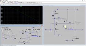
I'm trying positive current feedback in a compactron tube amplifier DC coupled via a current transformer, and it is very effective.
Hi Osvaldo,I'm trying positive current feedback in a compactron tube amplifier DC coupled via a current transformer, and it is very effective.
That sounds great !
Are you willing to show us the circuit diagram ?
Hans
I'm trying positive current feedback in a compactron tube amplifier DC coupled via a current transformer, and it is very effective.
Ahhh! You are building an oscillator for your transmitter?
Jan
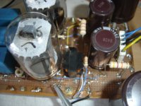
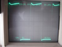
Yes, but the amplifier is still under development. As advance, look these pics.Hi Osvaldo,
That sounds great !
Are you willing to show us the circuit diagram ?
Hans
Attachments
Last edited:
Why?Ahhh! You are building an oscillator for your transmitter?
Jan
Why?
You said positive feedback? That makes an oscillator.
Jan
Not always. Is a Schmidt Trigger an oscillator? Is bootstrapped stage an oscillator? Clearly NO.
Still more NO in the context of negative voltage feedback.
Please, take a read to: A New Look at Positive Current Feedback, November 1957 Radio & TV News -
RF Cafe or search for the original text in the magazines.
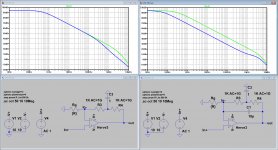
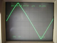
Do you see an oscillator/tions in this pics?
Still more NO in the context of negative voltage feedback.
Please, take a read to: A New Look at Positive Current Feedback, November 1957 Radio & TV News -
RF Cafe or search for the original text in the magazines.
Do you see an oscillator/tions in this pics?
Attachments
Last edited:
Not always. Is a Schmidt Trigger an oscillator? Is bootstrapped stage an oscillator? Clearly NO.
Still more NO in the context of negative voltage feedback.
Please, take a read to: A New Look at Positive Current Feedback, November 1957 Radio & TV News -
RF Cafe or search for the original text in the magazines.
Do you see an oscillator/tions in this pics?
Ahhh yes, an old technique. I read about it first in a 1956 article by a guy called Miller ;-) Do you know that article?
Use pos feedback to increase the gain and then negative feedback to get back to good linearity, using the excess gain. So the net feedback is negative - it must be for stability.
I thought you meant pos feedback only.
Interesting also that they (and also you I guess) use the term current feedback in the original meaning, not in the CFA meaning. More confusion to the people!
Edit: this is the article I meant: https://linearaudio.nl/sites/linearaudio.net/files/miller combined fb electronics march 1950.pdf . Fig 3 is of interest.
Jan
Last edited:
- Home
- Amplifiers
- Solid State
- Current Feedback Amplifiers, not only a semantic problem?