Konnichiwa,
The east german build TH315 "Schulze" 12" coaxial did exactly that. A flowresistance in FRONT of the cone. I worked a few month in the workshop/factory that made these and Schulze KSP-215....
Sayonara
Bill F. said:And not just behind the driver. Let's open our minds to the potential of flow resistant/acoustically absorbant materials in front of a wideband cone (around the perimeter), damping the fundamental resonance and absorbing the extraneous resonance signatures of the surround and standing waves along the outer circumference of the cone.
The east german build TH315 "Schulze" 12" coaxial did exactly that. A flowresistance in FRONT of the cone. I worked a few month in the workshop/factory that made these and Schulze KSP-215....
Sayonara
Interesting.
I guess there is nothing new under the sun.
Pictures?
I'm curious to what degree (thickness, location) they employed these materials.
I guess there is nothing new under the sun.
Pictures?
I'm curious to what degree (thickness, location) they employed these materials.
I just realized that voice coils could be made with more layers or turns, since the effects of voice coil inductance are eliminated with current drive... No more balancing BL with inductance!
Let's open our minds to the potential of flow resistant/acoustically absorbant materials in front of a wideband cone (around the perimeter), damping the fundamental resonance and absorbing the extraneous resonance signatures of the surround and standing waves along the outer circumference of the cone. I imagine this treatment could effectively treat beaming/lobing in the bargain, even as it eliminated diffraction effects from the cone/frame/baffle transition.
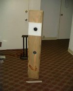
Been there, done this numerous times and it does all these things. Here's the unfinished 40-1354 towers I was building for a buddy at the time the Atlanta 2001 DIY Meet came around. No super tweeter was used since he's deaf above ~7kHz, though the 3/4" thick polyfil with HF 'window' combined with the ML-TL tuning and $0.98 whizzer tweak, the MLS measurement was +/-3dB from 40-12.5kHz. Since the polyfil damps the flimsy rubber surround so well and softly limits cone travel, it gives it the 'euphonic' type of soft clipping similar to a tube driven AlNiCo speaker when overdriven. Even with no mass loading or stable mounting base, overall, folks seemed to like them quite a bit even with the rolled off HF and were flat floored by how much smooth bass extension they had. At least one guy was convinced I had a bandpass 'sub' buried in them.
WRT cosmetics, eventually the polyfil was sprayed with a tan vinyl spray and covered with a ~matching expanded double knit material to make it look similar to one of those big foam grills of the '70s.
GM
Attachments
A conductor moving in a magnetic field has current flow in it that opposes the motion, which is fine for damping, but it also resists the movement of the diaphragm... How doesn't it sap energy?Kuei Yang Wang said:
Does it, I mean does it REALLY do that inherently?
Kuei Yang Wang said:The east german build TH315 "Schulze" 12" coaxial did exactly that. A flowresistance in FRONT of the cone. I worked a few month in the workshop/factory that made these and Schulze KSP-215....
Hi,
what do you think about quality of these drivers (th315)? Any datasheet?
I have two of them in very good condition (one without "resistance" on front
 ).
).Regards
Milan
Konnichiwa,
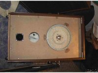
See attached. The ayer was fairly thin, maybe 5mm or so (this is now almost 2 decades ago!)....
I had a pair in their original enclosures, I thought them very good.
Sayonara
Bill F. said:I guess there is nothing new under the sun.
Pictures?
I'm curious to what degree (thickness, location) they employed these materials.
See attached. The ayer was fairly thin, maybe 5mm or so (this is now almost 2 decades ago!)....
moamps said:what do you think about quality of these drivers (th315)?
I had a pair in their original enclosures, I thought them very good.
Sayonara
Attachments
Konnichiwa,
Well, ANY form of damping saps energy, even electrical damping by the amplifier. This a fact of life. I understood that you implied that using a conductive voice coil former (perhaps with an aluminum alloy arranged EXACTLY for the right resistance with the right thickness) sapped energy in a much larger quantity than using any other methode ampluyed for the same amouunt of damping....
Sayonara
454Casull said:A conductor moving in a magnetic field has current flow in it that opposes the motion, which is fine for damping, but it also resists the movement of the diaphragm... How doesn't it sap energy?
Well, ANY form of damping saps energy, even electrical damping by the amplifier. This a fact of life. I understood that you implied that using a conductive voice coil former (perhaps with an aluminum alloy arranged EXACTLY for the right resistance with the right thickness) sapped energy in a much larger quantity than using any other methode ampluyed for the same amouunt of damping....
Sayonara
I had a pair in their original enclosures, I thought them very good.
What the **** is a cheap piezo doing in this box ???? 😉
Regards
Charles
Well, ANY form of damping saps energy, even electrical damping by the amplifier. This a fact of life.
There is still the possibility to use a form of mechanical damping that actually increases the efficiency of the driver. It uses some form of acoustical wideband tronsformer that increases coupling between driver and air ! 😕
😉 😉
Regards
Charles
Konnichiwa,
!!!???
What cheap piezo?
Ciao T
phase_accurate said:What the **** is a cheap piezo doing in this box ???? 😉
!!!???
What cheap piezo?
Ciao T
The black thingie to the left reminded me from a piezo tweeter ! 😉
Apart from that: If used properly they don't even sound that bad at all.
Regards
Charles
Apart from that: If used properly they don't even sound that bad at all.
Regards
Charles
Konnichiwa,
You mean to suggest that a Horn is actually an "acoustical transformer"? I thought that idea was illustrated to be ad absurdum the first time someone looked at the impedance plot of a driver in a horn?
You invariably see resonance ripples,caused by the fact that the horn is in fact a wideband, multiresonant halvewave "pipe"....
Sayonara
phase_accurate said:There is still the possibility to use a form of mechanical damping that actually increases the efficiency of the driver. It uses some form of acoustical wideband tronsformer that increases coupling between driver and air ! 😕
You mean to suggest that a Horn is actually an "acoustical transformer"? I thought that idea was illustrated to be ad absurdum the first time someone looked at the impedance plot of a driver in a horn?
You invariably see resonance ripples,caused by the fact that the horn is in fact a wideband, multiresonant halvewave "pipe"....
Sayonara
You invariably see resonance ripples,caused by the fact that the horn is in fact a wideband, multiresonant halvewave "pipe"....
I was indeed talking about a horn. Is there any literature available that is approaching the horn theory from the above viewpoint ?
Regards
Charles
Konnichiwa,
Not really. It is just the reverse view of things. Most theorists view horns as "acoustic transformers" and note the resonances to be "undesirable parasitics" which a "perfect" horn would not have. Yet even perfectly spherical front horns show impedance ripples within the operating range.
So I (and some others) decided to play devils advocate and view horns as "badly designed TL's/Pipes". Either view works pretty well, but one says that the resonances are a REQUIRED FEATURE of the function of the device which seems closer to the truth.
And actually, I should say that horns are Pipes combined with waveguides. The pipe (length of horn) makes the multiresonant system, the waveguide adjusts the drivers dispersion at frequencies where the drivers own dispersion is wider than that allowed by the waveguide, thus making the sound more directional and increasing SPL within the coverage range.
The one thing I fail is to observe in the impedance and SPL curve is the "transformer" operation.
Sayonara
phase_accurate said:I was indeed talking about a horn. Is there any literature available that is approaching the horn theory from the above viewpoint ?
Not really. It is just the reverse view of things. Most theorists view horns as "acoustic transformers" and note the resonances to be "undesirable parasitics" which a "perfect" horn would not have. Yet even perfectly spherical front horns show impedance ripples within the operating range.
So I (and some others) decided to play devils advocate and view horns as "badly designed TL's/Pipes". Either view works pretty well, but one says that the resonances are a REQUIRED FEATURE of the function of the device which seems closer to the truth.
And actually, I should say that horns are Pipes combined with waveguides. The pipe (length of horn) makes the multiresonant system, the waveguide adjusts the drivers dispersion at frequencies where the drivers own dispersion is wider than that allowed by the waveguide, thus making the sound more directional and increasing SPL within the coverage range.
The one thing I fail is to observe in the impedance and SPL curve is the "transformer" operation.
Sayonara
KYW,
The 'transformer' action is generally referred to as the fact that the pressure in the throat at the diafragma is much higher than at the horn mouth, so it transforms a low pressure wide area to a high pressure small area. One result, as I am sure you fully know, is a higher efficiency because the small diafragma is better 'matched' to the air load.
Again, I'm sure you know this even better than I do. So, what are you driving at?😀
Jan Didden
Konnichiwa,
Hmmm. That then gives rise to the question of the nature of sound. Is it (just) pressure?
One thing I would note is that if a horn actually DID "transform" acoustical impedances, not only would the impedance response curve be flat, without ripples, it should drastically reduce the cone excursion, compared to a driver with the same rear chamber and power input and frequency operating without the attached Horn. From my work with PA Enclosures I found this to be not the case.
Is it REALLY so? Can we not account equally for the gain in SPL by calaculating the reduction in radiation angle and including the resonances? I posit we can.
The view of the Horn as acoustic impedance transformer is WRONG. That's what I'm driving at. It is just not applicable, that's all.
The problem is that many concepts, such as the primitive view of open baffles / dipoles still promulgated in the literature and of course that of the horn as acoustic transformer (as opposed to waveguide and resonant acoustic amplifier) are siomply, demonstrably and clearly wrong, but are carried in academic and other literature as the Authors clearly merely repeating older material and neither make themselves aware of more recent material nor do experiements themselves which would easily illustrate the incorrectness of these views. Finally others parrot the inaccurate descriptions found in these textbooks as fact.
This is the classic academic approach, accept the argument of the published authority and avoid doing any experiments that could place you in troublesome opposition with published authority. Note, the accuracy or not of the notions presented is of no concern here.... Hell, I think most people in Audio still believe that Thiele/Small parameters are actually constants, simply because the published authorities choose to treat them as such, for the sake of the argument, never directly suggesting they where!!!!
Sayonara
janneman said:The 'transformer' action is generally referred to as the fact that the pressure in the throat at the diafragma is much higher than at the horn mouth, so it transforms a low pressure wide area to a high pressure small area.
Hmmm. That then gives rise to the question of the nature of sound. Is it (just) pressure?
One thing I would note is that if a horn actually DID "transform" acoustical impedances, not only would the impedance response curve be flat, without ripples, it should drastically reduce the cone excursion, compared to a driver with the same rear chamber and power input and frequency operating without the attached Horn. From my work with PA Enclosures I found this to be not the case.
janneman said:One result, as I am sure you fully know, is a higher efficiency because the small diafragma is better 'matched' to the air load.
Is it REALLY so? Can we not account equally for the gain in SPL by calaculating the reduction in radiation angle and including the resonances? I posit we can.
janneman said:Again, I'm sure you know this even better than I do. So, what are you driving at?
The view of the Horn as acoustic impedance transformer is WRONG. That's what I'm driving at. It is just not applicable, that's all.
The problem is that many concepts, such as the primitive view of open baffles / dipoles still promulgated in the literature and of course that of the horn as acoustic transformer (as opposed to waveguide and resonant acoustic amplifier) are siomply, demonstrably and clearly wrong, but are carried in academic and other literature as the Authors clearly merely repeating older material and neither make themselves aware of more recent material nor do experiements themselves which would easily illustrate the incorrectness of these views. Finally others parrot the inaccurate descriptions found in these textbooks as fact.
This is the classic academic approach, accept the argument of the published authority and avoid doing any experiments that could place you in troublesome opposition with published authority. Note, the accuracy or not of the notions presented is of no concern here.... Hell, I think most people in Audio still believe that Thiele/Small parameters are actually constants, simply because the published authorities choose to treat them as such, for the sake of the argument, never directly suggesting they where!!!!
Sayonara
Then the electrical resistivity of the former can be tailored for a certain amount of damping?Kuei Yang Wang said:Konnichiwa,
Well, ANY form of damping saps energy, even electrical damping by the amplifier. This a fact of life. I understood that you implied that using a conductive voice coil former (perhaps with an aluminum alloy arranged EXACTLY for the right resistance with the right thickness) sapped energy in a much larger quantity than using any other methode ampluyed for the same amouunt of damping....
Sayonara
Hmm... sounds good. I also realized that using a hydraulic damper would also sap energy, since energy is required to push the fluid through the valves.
Konnichiwa,
Who said it couldnt? Just select the right thickness of the right alloy. Make the alloy somewhat manetic (aluminum nickel alloy?) and you will also have the restoring force and voice coil centering solved without needing any spider or other rear structure 9the hartley solution).
Even if you use a shortcircuit voice coil (liek shortcircuited by the amplifiers low output impedance) you sap energy. No matter how you apply the damping, the same amount of damping leads to the same losses. The only question is where you do the dirty work.
Given how much the Bl factor varies with driver excursion and given how much the voice coil resistance changes with signal level I would argue that electrical damping through the amplifier was alwayas a **** poor choice to start with....
Sayonara
454Casull said:Then the electrical resistivity of the former can be tailored for a certain amount of damping?
Who said it couldnt? Just select the right thickness of the right alloy. Make the alloy somewhat manetic (aluminum nickel alloy?) and you will also have the restoring force and voice coil centering solved without needing any spider or other rear structure 9the hartley solution).
454Casull said:Hmm... sounds good. I also realized that using a hydraulic damper would also sap energy, since energy is required to push the fluid through the valves.
Even if you use a shortcircuit voice coil (liek shortcircuited by the amplifiers low output impedance) you sap energy. No matter how you apply the damping, the same amount of damping leads to the same losses. The only question is where you do the dirty work.
Given how much the Bl factor varies with driver excursion and given how much the voice coil resistance changes with signal level I would argue that electrical damping through the amplifier was alwayas a **** poor choice to start with....
Sayonara
Hmm, and with ferrofluid in the gap, that takes care of the thermal and centering issues of the voice coil...Kuei Yang Wang said:Konnichiwa,
Who said it couldnt? Just select the right thickness of the right alloy. Make the alloy somewhat manetic (aluminum nickel alloy?) and you will also have the restoring force and voice coil centering solved without needing any spider or other rear structure 9the hartley solution).
Even if you use a shortcircuit voice coil (liek shortcircuited by the amplifiers low output impedance) you sap energy. No matter how you apply the damping, the same amount of damping leads to the same losses. The only question is where you do the dirty work.
Given how much the Bl factor varies with driver excursion and given how much the voice coil resistance changes with signal level I would argue that electrical damping through the amplifier was alwayas a **** poor choice to start with....
Sayonara
- Home
- Loudspeakers
- Multi-Way
- Current Driven Loudspeakers and Tranconductance Amplifiers