Konnichiwa,
EXACTLY.
Now, as the excursion increases both restoring force and driving force go down, while in normal speakers the restoring force increases with excursion, leading to increased distortion. So, what you see as "problem" is in fact EXACTLY what we want!
Well, there are other magnet structures that yield a pretty constant BL with excursion often seen in the really top grade speakers of the 1950's and early 60's and Hartley may very well use one of these.
However, it is important to remember that a restoring force that varies equally as BL varies is a "good thing" and will be always applicable, regardless if one makes a motor with constant BL or not.
Sayonara
454Casull said:According to a certain site found using a Google search ("Hartley magnetic suspension"), Hartley's magnetic suspension uses a layer of powdered iron behind the voice coil. The problem I see is the returning force gets weaker and weaker as excursion increases, just as BL vs excursion does in most drivers.
EXACTLY.
Now, as the excursion increases both restoring force and driving force go down, while in normal speakers the restoring force increases with excursion, leading to increased distortion. So, what you see as "problem" is in fact EXACTLY what we want!
454Casull said:Unless, of course, the driver motor was built using an XBL^2 topology, in which the returning force would be roughly flat across linear excursion... no?
Well, there are other magnet structures that yield a pretty constant BL with excursion often seen in the really top grade speakers of the 1950's and early 60's and Hartley may very well use one of these.
However, it is important to remember that a restoring force that varies equally as BL varies is a "good thing" and will be always applicable, regardless if one makes a motor with constant BL or not.
Sayonara
Konnichiwa,
Does your model account for the non-linearity in BL, Eddy current losses and voicecoil heating.
Then you model has been simplified beyond usuability.The EMF and the electrical damping derived from that is proportional to cone velocity, voicecoil position in the gap and voicecoil temperature.
You feel it is "very hard"? Are you sure? Even this thread already contained some suggestions that would provide a "self damping" driveunit with a comparably linear damping directly proportinal to the voicecoil velocity.
In my view we trade several bad things for the responsibility to manage ONE bad thing responsibly. Less variables usually mean a reduction in the complexity of the problems to be resolved.
This brings us back to MFB and the problematic of how to sense the cone velocity accuratly. Most of the schemes used and proposed so far either suffer from insufficient linearity or are too frequency response limited to be really usefull.
ANd hope and pray that the dustcap is neither flexible nor imbued with any hysteresis. And of cource that the senser has no hysteresis and is linear.
That, except the point about cheapness is a thesis that cannot be accepted as true at all, sorry. Piezo elements suffer from exactly the things I suggested above which would make a bad sensor.
Sayonara
Pjotr said:Appended an electro-mechanical model of an electro dynamic loudspeaker. This model shows more direct what is going on in a loudspeaker than the model of T&S.
Does your model account for the non-linearity in BL, Eddy current losses and voicecoil heating.
Pjotr said:What can be seen is that damping is a force proportional to cone velocity.
Then you model has been simplified beyond usuability.The EMF and the electrical damping derived from that is proportional to cone velocity, voicecoil position in the gap and voicecoil temperature.
Pjotr said:Now is raising the mechanical loss a viable solution the get proper damping? IMHO we are trading bad things for other bad things then. It is very hard to get large mechanical damping ( = friction) with low distortion.
You feel it is "very hard"? Are you sure? Even this thread already contained some suggestions that would provide a "self damping" driveunit with a comparably linear damping directly proportinal to the voicecoil velocity.
In my view we trade several bad things for the responsibility to manage ONE bad thing responsibly. Less variables usually mean a reduction in the complexity of the problems to be resolved.
Pjotr said:A better approach looks sensing cone velocity and feed back that to the input of the current amp.
This brings us back to MFB and the problematic of how to sense the cone velocity accuratly. Most of the schemes used and proposed so far either suffer from insufficient linearity or are too frequency response limited to be really usefull.
Pjotr said:Better use an acceleration sensor mounted on the dust cap
ANd hope and pray that the dustcap is neither flexible nor imbued with any hysteresis. And of cource that the senser has no hysteresis and is linear.
Pjotr said:Piezo disks senses acceleration with pretty low distortion and are cheap.
That, except the point about cheapness is a thesis that cannot be accepted as true at all, sorry. Piezo elements suffer from exactly the things I suggested above which would make a bad sensor.
Sayonara
Kuei Yang Wang said:Konnichiwa,
Does your model account for the non-linearity in BL, Eddy current losses and voicecoil heating.
Then you model has been simplified beyond usuability.The EMF and the electrical damping derived from that is proportional to cone velocity, voicecoil position in the gap and voicecoil temperature.
You feel it is "very hard"? Are you sure? Even this thread already contained some suggestions that would provide a "self damping" driveunit with a comparably linear damping directly proportinal to the voicecoil velocity.
In my view we trade several bad things for the responsibility to manage ONE bad thing responsibly. Less variables usually mean a reduction in the complexity of the problems to be resolved.
This brings us back to MFB and the problematic of how to sense the cone velocity accuratly. Most of the schemes used and proposed so far either suffer from insufficient linearity or are too frequency response limited to be really usefull.
ANd hope and pray that the dustcap is neither flexible nor imbued with any hysteresis. And of cource that the senser has no hysteresis and is linear.
That, except the point about cheapness is a thesis that cannot be accepted as true at all, sorry. Piezo elements suffer from exactly the things I suggested above which would make a bad sensor.
Sayonara
Dear KYW
Thank you very much for your negative feedback, very helpful
 IMHO there is no need to show open doors and ask questions which has obvious answers in such a bashing way. I regarded you to know better 🙁
Maybe you do better to read again my post and get what I intended to say.
What I posted is in fact a summary from what was published in the AES journals in the past years concerning current drive. That publications showed more or less good results.
Seems you don’t appreciate a different view. Ok continue with adding mechanical friction to dampen a loudspeaker. Curious about your results.
Regards
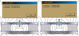
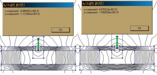
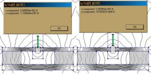
Just to clarify the behavior of magnetic ring suspensions, here is a series of FEMM sims of a segment of pure iron in a magnetic gap moving through steps of outward excursion.
Look at the Y-component results of the force integrals (ignore X). The values are negative when the net force is pulling the iron segment downward.
First attachment: segment centered in gap, and segment displaced outward 0.2"
Look at the Y-component results of the force integrals (ignore X). The values are negative when the net force is pulling the iron segment downward.
First attachment: segment centered in gap, and segment displaced outward 0.2"
Attachments
Konnichiwa,
Hmmm. Maybe a look at the Hartley Implementation will help?
http://patft.uspto.gov/netacgi/nph-Parser?Sect1=PTO1&Sect2=HITOFF&d=PALL&p=1&u=/netahtml/srchnum.htm&r=1&f=G&l=50&s1=3160716.WKU.&OS=PN/3160716&RS=PN/3160716
Sayonara
Bill F. said:Just to clarify the behavior of magnetic ring suspensions, here is a series of FEMM sims of a segment of pure iron in a magnetic gap moving through steps of outward excursion.
Hmmm. Maybe a look at the Hartley Implementation will help?
http://patft.uspto.gov/netacgi/nph-Parser?Sect1=PTO1&Sect2=HITOFF&d=PALL&p=1&u=/netahtml/srchnum.htm&r=1&f=G&l=50&s1=3160716.WKU.&OS=PN/3160716&RS=PN/3160716
Sayonara
Thanks for digging up that patent, Thorsten. Interesting reading. I doff my hat to the genius of Mr. Luth!
The patent appears to confirm what I was imagining about the function of the Hartley/Luth magnetic suspension, so I believe my simulations are still applicable.
I was interested that the VC former in the preferred embodiment of the design appears to be based on an aluminum tube with no mention of a slit, so it would be an effective eddy-current damper. I wonder if this is at least partly responsible for the lack of ringing at the end of the time/displacement graphs they use to illustrate the superiority of the magnetic suspension (with large dia. spider for radial centering) over a tighter spider suspension.
Konnichiwa,
Yes, basically, the restoring force is allways directly proportional to the force attempting to remove the voice coil from the zero position.
Yup. It also illustrates to all the nay sayers that eddy current damping is not a "bad thing", as few who have experienced Hartley Drivers would argue that they "sound bad".
I would think so. Basically, combine a magnetic suspension and suitably arranged Aluminum VC with a suitable voicecoil in a magnet system with a reasonably well linearised filed and you have a driver that should do very well, if the acoustic system is build as well as the electromagentic one..
Sayonara
Bill F. said:The patent appears to confirm what I was imagining about the function of the Hartley/Luth magnetic suspension, so I believe my simulations are still applicable.
Yes, basically, the restoring force is allways directly proportional to the force attempting to remove the voice coil from the zero position.
Bill F. said:I was interested that the VC former in the preferred embodiment of the design appears to be based on an aluminum tube with no mention of a slit, so it would be an effective eddy-current damper.
Yup. It also illustrates to all the nay sayers that eddy current damping is not a "bad thing", as few who have experienced Hartley Drivers would argue that they "sound bad".
Bill F. said:I wonder if this is at least partly responsible for the lack of ringing at the end of the time/displacement graphs they use to illustrate the superiority of the magnetic suspension (with large dia. spider for radial centering) over a tighter spider suspension.
I would think so. Basically, combine a magnetic suspension and suitably arranged Aluminum VC with a suitable voicecoil in a magnet system with a reasonably well linearised filed and you have a driver that should do very well, if the acoustic system is build as well as the electromagentic one..
Sayonara
On the subject of measuring cone displacement/velocity , I wondered whether using an optical measuring system
might be a good idea.
For instance, a module containing a couple of laser diodes and detectors aligned to a target
on the cone in such a way ,that as the cone moved the two focused points would move in relation to one another.
Maybe something like this could be used to provide position and velocity data?
Just a thought
Setmenu
Hi Setmenu,
There is a relatively simple optical way to measure position without the need of a laser, it is in fact quite old and a simple light spot will do. It is very fast, simple and has high resolution. Have a look here:
http://www.on-trak.com/theory.html
With a simple optical technique called “triangulation” you can measure distance with those devices.
However those devices senses position (or displacement). To derive velocity from that you need to differentiate the position signal, something you don’t want to because of noise.
Cheers 😉
Pjotr said:Hi Setmenu,
There is a relatively simple optical way to measure position without the need of a laser, it is in fact quite old and a simple light spot will do. It is very fast, simple and has high resolution. Have a look here:
http://www.on-trak.com/theory.html
With a simple optical technique called “triangulation” you can measure distance with those devices.
However those devices senses position (or displacement). To derive velocity from that you need to differentiate the position signal, something you don’t want to because of noise.
Cheers 😉
Hi Pjotr
Thanks for that link, looks interesting.
I guess every method would have it's pros and cons....
This is an interesting thread, though somewhat over my head
 .
.I am a bit of a planar/ribbon transducer fiend myself,
especially where headphones are concerned 😀
Cheers
Setmenu
Nice ideas, but...
With any feedback device and associated signal processing, there will be phase shifts which will affect closed loop stability. The more processing involved, the more difficult it will be to get a stable system.
Just my thoughts on it..🙂
With any feedback device and associated signal processing, there will be phase shifts which will affect closed loop stability. The more processing involved, the more difficult it will be to get a stable system.
Just my thoughts on it..🙂
Re: Nice ideas, but...
Don’t worry too much, attached a picture of the (simulated) loop gain of a current driven Peerless HDS 164 woofer in a 20L closed box. Total Q was aligned to 0.71. Velocity feedback was taken from acceleration integrated by a 1 Hz, 1st order low pass filter. No signs of danger show up 🙂
Back to what a dynamic loudspeaker is in fact. If we ignore the acoustical output of the loudspeaker, which power is very low concerning the total powers involved (exempt for a horn loaded speaker), a dynamic loudspeaker is nothing else than an oscillatory second order mass-spring system. Such a system stores a lot of energy around its resonant frequency Fs. When we drive it with a voltage the speaker takes much less energy around Fs due the back EMF which is highest at Fs. Around Fs the impedance raises a lot and we can say the speaker takes the current that it needs keeping the stored energy within reasonable bounds. That way it is kind of “self adapting”.
Now if we drive it with a current we are forcing much too much energy into the loudspeaker around Fs, resulting in a sharp response peak around Fs and oscillatory behaviour (“ringing”) in response of a step input. Now what can we do about it? We can dissipate this excessive energy into heat by means of heavily braking the system as KYW proposes, either by means of viscous damping or by means of eddy current braking. This in fact lowers the mechanical Q factor. During the last decades many people reported that loudspeakers with low mechanical Q simply sound dull, sound “slow” and/or are lacking fine detail. It is not for nothing that modern speaker manufactures tend to make Qm as high as possible. A high Qm means low mechanical losses.
Instead of converting the excessive power put into the loudspeaker into heat by means of mechanical damping, we do better to NOT put excessive energy into the speaker IMHO.
There are two ways to accomplish this:
1/ Putting a notch filter in front of the amplifier, compensating for the peaking around Fs. A suitable filter is a bi-quadratic filter like a LW transform. However this is tricky at high values of Qm.
2/ Using MFB by sensing cone velocity. This is a well-proven concept.
Turning the excessive power around Fs into heat by using heavy mechanical damping is putting the horse behind the cart IMHO.
Cheers 😉
johnnyx said:With any feedback device and associated signal processing, there will be phase shifts which will affect closed loop stability. The more processing involved, the more difficult it will be to get a stable system.
Don’t worry too much, attached a picture of the (simulated) loop gain of a current driven Peerless HDS 164 woofer in a 20L closed box. Total Q was aligned to 0.71. Velocity feedback was taken from acceleration integrated by a 1 Hz, 1st order low pass filter. No signs of danger show up 🙂
Back to what a dynamic loudspeaker is in fact. If we ignore the acoustical output of the loudspeaker, which power is very low concerning the total powers involved (exempt for a horn loaded speaker), a dynamic loudspeaker is nothing else than an oscillatory second order mass-spring system. Such a system stores a lot of energy around its resonant frequency Fs. When we drive it with a voltage the speaker takes much less energy around Fs due the back EMF which is highest at Fs. Around Fs the impedance raises a lot and we can say the speaker takes the current that it needs keeping the stored energy within reasonable bounds. That way it is kind of “self adapting”.
Now if we drive it with a current we are forcing much too much energy into the loudspeaker around Fs, resulting in a sharp response peak around Fs and oscillatory behaviour (“ringing”) in response of a step input. Now what can we do about it? We can dissipate this excessive energy into heat by means of heavily braking the system as KYW proposes, either by means of viscous damping or by means of eddy current braking. This in fact lowers the mechanical Q factor. During the last decades many people reported that loudspeakers with low mechanical Q simply sound dull, sound “slow” and/or are lacking fine detail. It is not for nothing that modern speaker manufactures tend to make Qm as high as possible. A high Qm means low mechanical losses.
Instead of converting the excessive power put into the loudspeaker into heat by means of mechanical damping, we do better to NOT put excessive energy into the speaker IMHO.
There are two ways to accomplish this:
1/ Putting a notch filter in front of the amplifier, compensating for the peaking around Fs. A suitable filter is a bi-quadratic filter like a LW transform. However this is tricky at high values of Qm.
2/ Using MFB by sensing cone velocity. This is a well-proven concept.
Turning the excessive power around Fs into heat by using heavy mechanical damping is putting the horse behind the cart IMHO.
Cheers 😉
Attachments
Re: Re: Nice ideas, but...
Konnichiwa,
I am first and foremost looking at generating a linear force to drive the mass spring system. Dealing with the stored energy is another issue.
Can we? The back emf is higher because the system becomes more efficient SENSITIVELY and ONLY around resonance.
Most people with little overview seem to think all important stuff in speakers happens at resonance. I propose to ignore the resonance as a competently designed system will have it's resonance MECHANICALLY and LINEARY critically damped, or damepd to whatever desired degree.
ONLY if we have designed a speaker system with a non-flat power response.
I find this rather hard to believe. Some of the reportedly least "dull" and "slow" sounding drivers have a very low Qm, compared to average systems which seem to minimise inherent damping and then ferverently hope that the amplifier desiger will rescue their poorely designed drivers.
Now, let's have a look at drivers that have comparably low Qm and sound reputedly excellent:
Lowthers, correctly applied (Qm 3...4)
Hartley
Many Seas units, including those used by one of the major speaker designers to whome I believe the original misinformation quoted above was MISATTRIBUTED, Mr. Joachim "Audio Physics" Gerhardt. That includes the top of the range Seas units recommended by Mr Linkwitz for the Orion and by many others (Qm 2....3) and of course the Drivers in one of the first true "high resolution" High End Speakers, the Wilson Watt.
Many Dynaudio units, including Esotec Woofers and of course those used in the Wilson Puppy Subwoofer.(Qms usually <2)
Most earlier Scan Speak units, including the seminal 15W8545 (usually 1.5...<3)
In fact, with very few exceptions (notably only the scan speak "revelator" woofers) no premium grade driver maker seems to be attempting to reduce mechanical losses, on the contrary, mostly the Qm has been creeping dwn over year and the Qe upwards.
So, in most cases the drive units made by the reputedly best manufacturers featrue a low Qm and thus a high mechanical loss. Maybe you wish to first research such statements as you make above, to avoid embarresment.
Yup, and easy and cheap engineering.
See above, IT IS NOT for nothing that modern premium grade speaker amnufacturers tend to make Qm quite low, compared to cheap dreck usually made, where Qm tends to be sky high.
Well, if we have a well engineered speaker it will have have a flat power sensitivity with frequency and then there is no problem. If we fail to design our drive unit competently (in other words if we bild a car with spring suspension and omit the shock dampers) then we have a problem AT THE RESONANCE and ONLY at and around the resonance. There are no problem if the driver is operatedsignificantly above or below the resonance.
Are you sure you cannot think of any more. I'm disappointed.
Which need not be a problem, as most modern premium grade speaker drivers feature moderate Qm's.
I have no beef per se with MFB, however, it has a large number of flaws inherent to it , mainly the same of course as with any feedback system.
Yes, MFB damps the cone motion by electronic feedback, an aluminum voice coil former does so by electromenchanical feedback. I will agree that the damping effect at resonance will be somewhat less linear than that of MFB, but over most the drivers operating range this will not matter ever which way.
One system of damping the resonance requires a complex, inherently instable active feedback system with much added complexity and cost, the other requires a minimal change to existing speaker driver engineering and is available in effect at zero cost and is only VERY MARGINALLY inferior in performance.
For an extreme high end system it may very well be desirable to apply some form of MFB, for other systems one may very well be overall better of to simply apply sufficient inherent damping to the driver.
Now self damping drive units and chip based current amplifiers can be implemented in anything, from Boom Box over TV's to Mid-Fi systems. More complex systems may very well remain the preserve of of discrete amplifiers, MFB and the like.
However, I suspect to most DIY'ers the solution of having a drive unit that takes more or less care of itself with possibly the addition of increasing mechanical losses empirically in the box (or using dipoles) will be much easier and more effective to implement than MFB (I also worked on/with MFB in the 1980's - the temptation to get real deep bass with very small boxes and drivers was irresistable).
Nope, it is putting the horse in front of the cart in a very simple system. MFB is putting the horse behind the cart and then working an extended system of pulleys and controls to regain an operational vehicle, a, so to speak, Rube Goldberg machine.
Here we have opposing fundamental approaches to design. I prefer inherent simplicity and elegance (eg not make any mistakes in the first place) and you prefer very complex solutions with at best marginal improvements over the brutally simple engineering. If you so wish, my engineering approach is closer to russian and yours to american.... ;-)
Sayonara
Konnichiwa,
Pjotr said:a dynamic loudspeaker is nothing else than an oscillatory second order mass-spring system. Such a system stores a lot of energy around its resonant frequency Fs.
I am first and foremost looking at generating a linear force to drive the mass spring system. Dealing with the stored energy is another issue.
Pjotr said:When we drive it with a voltage the speaker takes much less energy around Fs due the back EMF which is highest at Fs. Around Fs the impedance raises a lot and we can say the speaker takes the current that it needs keeping the stored energy within reasonable bounds.
Can we? The back emf is higher because the system becomes more efficient SENSITIVELY and ONLY around resonance.
Most people with little overview seem to think all important stuff in speakers happens at resonance. I propose to ignore the resonance as a competently designed system will have it's resonance MECHANICALLY and LINEARY critically damped, or damepd to whatever desired degree.
Pjotr said:Now if we drive it with a current we are forcing much too much energy into the loudspeaker around Fs, resulting in a sharp response peak around Fs and oscillatory behaviour (“ringing”) in response of a step input.
ONLY if we have designed a speaker system with a non-flat power response.
Pjotr said:Now what can we do about it? We can dissipate this excessive energy into heat by means of heavily braking the system as KYW proposes, either by means of viscous damping or by means of eddy current braking. This in fact lowers the mechanical Q factor. During the last decades many people reported that loudspeakers with low mechanical Q simply sound dull, sound “slow” and/or are lacking fine detail.
I find this rather hard to believe. Some of the reportedly least "dull" and "slow" sounding drivers have a very low Qm, compared to average systems which seem to minimise inherent damping and then ferverently hope that the amplifier desiger will rescue their poorely designed drivers.
Now, let's have a look at drivers that have comparably low Qm and sound reputedly excellent:
Lowthers, correctly applied (Qm 3...4)
Hartley
Many Seas units, including those used by one of the major speaker designers to whome I believe the original misinformation quoted above was MISATTRIBUTED, Mr. Joachim "Audio Physics" Gerhardt. That includes the top of the range Seas units recommended by Mr Linkwitz for the Orion and by many others (Qm 2....3) and of course the Drivers in one of the first true "high resolution" High End Speakers, the Wilson Watt.
Many Dynaudio units, including Esotec Woofers and of course those used in the Wilson Puppy Subwoofer.(Qms usually <2)
Most earlier Scan Speak units, including the seminal 15W8545 (usually 1.5...<3)
In fact, with very few exceptions (notably only the scan speak "revelator" woofers) no premium grade driver maker seems to be attempting to reduce mechanical losses, on the contrary, mostly the Qm has been creeping dwn over year and the Qe upwards.
So, in most cases the drive units made by the reputedly best manufacturers featrue a low Qm and thus a high mechanical loss. Maybe you wish to first research such statements as you make above, to avoid embarresment.
Pjotr said:It is not for nothing that modern speaker manufactures tend to make Qm as high as possible. A high Qm means low mechanical losses.
Yup, and easy and cheap engineering.
See above, IT IS NOT for nothing that modern premium grade speaker amnufacturers tend to make Qm quite low, compared to cheap dreck usually made, where Qm tends to be sky high.
Pjotr said:Instead of converting the excessive power put into the loudspeaker into heat by means of mechanical damping, we do better to NOT put excessive energy into the speaker IMHO.
Well, if we have a well engineered speaker it will have have a flat power sensitivity with frequency and then there is no problem. If we fail to design our drive unit competently (in other words if we bild a car with spring suspension and omit the shock dampers) then we have a problem AT THE RESONANCE and ONLY at and around the resonance. There are no problem if the driver is operatedsignificantly above or below the resonance.
Pjotr said:There are two ways to accomplish this:
Are you sure you cannot think of any more. I'm disappointed.
Pjotr said:1/ Putting a notch filter in front of the amplifier, compensating for the peaking around Fs. A suitable filter is a bi-quadratic filter like a LW transform. However this is tricky at high values of Qm.
Which need not be a problem, as most modern premium grade speaker drivers feature moderate Qm's.
Pjotr said:2/ Using MFB by sensing cone velocity. This is a well-proven concept.
I have no beef per se with MFB, however, it has a large number of flaws inherent to it , mainly the same of course as with any feedback system.
Yes, MFB damps the cone motion by electronic feedback, an aluminum voice coil former does so by electromenchanical feedback. I will agree that the damping effect at resonance will be somewhat less linear than that of MFB, but over most the drivers operating range this will not matter ever which way.
One system of damping the resonance requires a complex, inherently instable active feedback system with much added complexity and cost, the other requires a minimal change to existing speaker driver engineering and is available in effect at zero cost and is only VERY MARGINALLY inferior in performance.
For an extreme high end system it may very well be desirable to apply some form of MFB, for other systems one may very well be overall better of to simply apply sufficient inherent damping to the driver.
Now self damping drive units and chip based current amplifiers can be implemented in anything, from Boom Box over TV's to Mid-Fi systems. More complex systems may very well remain the preserve of of discrete amplifiers, MFB and the like.
However, I suspect to most DIY'ers the solution of having a drive unit that takes more or less care of itself with possibly the addition of increasing mechanical losses empirically in the box (or using dipoles) will be much easier and more effective to implement than MFB (I also worked on/with MFB in the 1980's - the temptation to get real deep bass with very small boxes and drivers was irresistable).
Pjotr said:Turning the excessive power around Fs into heat by using heavy mechanical damping is putting the horse behind the cart IMHO.
Nope, it is putting the horse in front of the cart in a very simple system. MFB is putting the horse behind the cart and then working an extended system of pulleys and controls to regain an operational vehicle, a, so to speak, Rube Goldberg machine.
Here we have opposing fundamental approaches to design. I prefer inherent simplicity and elegance (eg not make any mistakes in the first place) and you prefer very complex solutions with at best marginal improvements over the brutally simple engineering. If you so wish, my engineering approach is closer to russian and yours to american.... ;-)
Sayonara
For a current-driven drive unit, is Qts roughly equal to Qm throughout the entire frequency range, or just near Fs?
Konnichiwa,
I am not sure I follow. The whole set of Q parameters describe the behaviour at the fundamental resonance. As such they are of any relevance only to descrive the resonant behaviour of the drive unit at the resonance frequancy Fs.
Sayonara
454Casull said:For a current-driven drive unit, is Qts roughly equal to Qm throughout the entire frequency range, or just near Fs?
I am not sure I follow. The whole set of Q parameters describe the behaviour at the fundamental resonance. As such they are of any relevance only to descrive the resonant behaviour of the drive unit at the resonance frequancy Fs.
Sayonara
I knew that, but I suppose I glossed over it. 🙂 What I mean is, does the electrical damping of a voltage-driven drive unit disappear when it's driven with a current source - i.e. do current-drive drive units reliant only on mechanical damping and not electrical?Kuei Yang Wang said:Konnichiwa,
I am not sure I follow. The whole set of Q parameters describe the behaviour at the fundamental resonance. As such they are of any relevance only to descrive the resonant behaviour of the drive unit at the resonance frequancy Fs.
Sayonara
The short answer: Yes. 🙂 (Unless you employ an eddy-current damper, like a continuous aluminum former, which supplys electro-mechanical damping, much like a low-Zo amp.)
But if you're worried about losing damping behavior much above Fs, set your mind at ease, because electrical damping doesn't usually play much of a part there anyway.
In the bandwidth between resonance and the cone's first standing wave, the cone/VC system is mass controlled, meaning residual energy tends to convert to the resonant frequency. A good current-drive loudspeaker should of course be properly damped at resonance.
Above the frequency of the first standing wave (which is determined by the speed of sound propagation through the cone material), the internal lossiness of the cone material and the degree of resistive termination supplied by the surround serve to damp potential resonance.
Even if the motor is designed for a high degree of electrical damping, the VC/former usually presents a big impedence mismatch to a high-frequency cone reflection coming back down from the surround, so the wave will simply reflect again and transmit little energy to the VC to damp.
Re: Re: Re: Nice ideas, but...
Yup, all those units are still not properly damped when driven with a current source and they all exhibit an unwanted response around Fs then. So regarding your words: "a competently designed system will have it's resonance MECHANICALLY and LINEARY critically damped, or damepd to whatever desired degree." no manufacturer has managed to produce a "competently designed" loudspeaker. It’s a shame 😱
I leave the rest of your comments up to you. I wonder if you ever build a good working MFB system yourself? I guess not.
Go on and spend your energy to bring up a working proof of concept of a critically mechanical damped loudspeaker unit that also sounds GOOD. Maybe we can learn something ...
Cheers 😉
Kuei Yang Wang said:Now, let's have a look at drivers that have comparably low Qm and sound reputedly excellent:
Lowthers, correctly applied (Qm 3...4)
Hartley
Many Seas units, including those used by one of the major speaker designers to whome I believe the original misinformation quoted above was MISATTRIBUTED, Mr. Joachim "Audio Physics" Gerhardt. That includes the top of the range Seas units recommended by Mr Linkwitz for the Orion and by many others (Qm 2....3) and of course the Drivers in one of the first true "high resolution" High End Speakers, the Wilson Watt.
Many Dynaudio units, including Esotec Woofers and of course those used in the Wilson Puppy Subwoofer.(Qms usually <2)
Most earlier Scan Speak units, including the seminal 15W8545 (usually 1.5...<3)
In fact, with very few exceptions (notably only the scan speak "revelator" woofers) no premium grade driver maker seems to be attempting to reduce mechanical losses, on the contrary, mostly the Qm has been creeping dwn over year and the Qe upwards.
So, in most cases the drive units made by the reputedly best manufacturers featrue a low Qm and thus a high mechanical loss. Maybe you wish to first research such statements as you make above, to avoid embarresment
Yup, all those units are still not properly damped when driven with a current source and they all exhibit an unwanted response around Fs then. So regarding your words: "a competently designed system will have it's resonance MECHANICALLY and LINEARY critically damped, or damepd to whatever desired degree." no manufacturer has managed to produce a "competently designed" loudspeaker. It’s a shame 😱
I leave the rest of your comments up to you. I wonder if you ever build a good working MFB system yourself? I guess not.
Go on and spend your energy to bring up a working proof of concept of a critically mechanical damped loudspeaker unit that also sounds GOOD. Maybe we can learn something ...
Cheers 😉
- Home
- Loudspeakers
- Multi-Way
- Current Driven Loudspeakers and Tranconductance Amplifiers