It isn't.
But this is what I get, and this is not the only one:
https://www.diyaudio.com/community/threads/the-elsinore-project-thread.97043/page-261#post-7259982
Edit: Textbooks, I would love to see.
But this is what I get, and this is not the only one:
https://www.diyaudio.com/community/threads/the-elsinore-project-thread.97043/page-261#post-7259982
Edit: Textbooks, I would love to see.
Sometimes it takes very little to say what's important. Less can be more, and it reduces the chance someone will misunderstand something.
The part covering resonance is over 1,000 pages, unfortunately.Textbooks, I would love to see.
Joe, the current from "current amplifier" is due to high voltage over high impedance. Its the impedance in the circuit that differentiates "voltage amplifier" and "current amplifier". "Current amplifier" is misnomer here although that is what it is the effects using one, reduced distortion and electronic damping, is not properties of the amplifier or the current but the high circuit impedance. High circuit impedance changes how the driver behaves, current in the circuit is not manipulated by driver as much as with low circuit impedance. This is the confusion here, impedance in the circuit makes difference on the currents in the circuit. Thinking impedance and all is very clear.
KSTR explains nicely what the electronic damping is. When circuit impedance is increased electronic damping erodes quickly. Its all in the impedance. If circuit impedance doubles from drivers impedance alone, at some particular frequency like in drivers resonance, the current in the circuit with drivers back-EMF voltage cuts in half.
See this image series that shows what happens as circuit impedance is increased by manipulating amplifier output impedance. Cycle it through with keyboard arrow buttons.
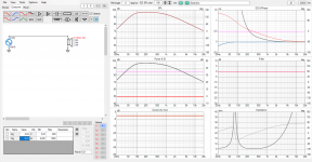
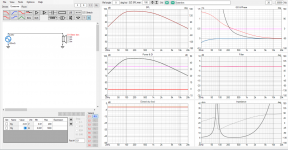
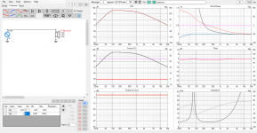
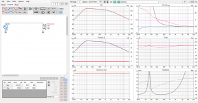
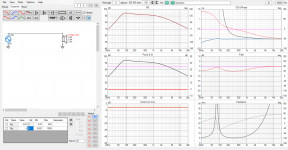
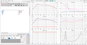
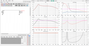
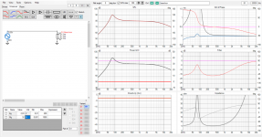
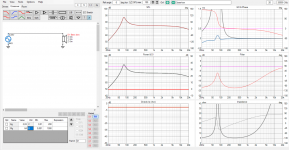
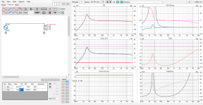
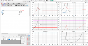
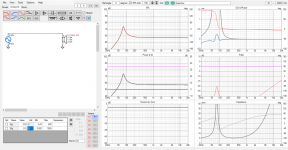
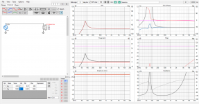
See, there is no line between current or voltage amplifier, all we have is circuit impedance.
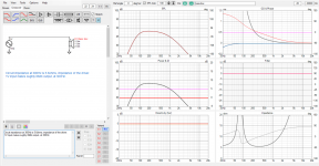
To reach particular acoustic output at some frequency some particular current needs to flow through voice coil. When circuit impedance is increased, we need higher voltage to make same current flow in the circuit, to reach same acoustic output at some particular frequency. See this example. It is 1V source, lets inspect output at 300Hz, it depends on impedance at 300Hz which in this case is 5.6 ohms.
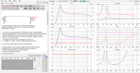
If we then increase circuit impedance by using amplifier whose output impedance is 94,4ohms to make 100ohms total at 300Hz we can use the impedance to calculate what voltage we need to get same current flowing, same acoustic output, at 300Hz.
Whats the nugget of this post?
Electronic damping is from driver velocity generated back-EMF voltage, KSTR shows the math and its available anywhere else you look for it. When circuit impedance is increased this back-EMF voltage makes less and less current in the circuit, as can be reasoned from the above demonstrations. We would have to increase voltage of the back-EMF to maintain electronic damping with high circuit impedance, this is not happening because velocity stays the same for given force, so the electronic damping is lost when circuit impedance is increased (like with using current amplifier without low impedance shunt). Its not lost completely because impedance is finite, but almost.
In circuit analysis ideal current amplifier is open circuit, ideal voltage amplifier is a short circuit, KSTR refers to these for easy though processes. In reality current amplifier is Nortons equivalent, some finite impedance in parallel with ideal current source = series impedance for rest of the circuit. Same goes for voltage amplifier, its Thevenins equivalent, ideal voltage source with some series impedance = series impedance for rest of the circuit.
This stuff is taught in college physics, although not in loudspeaker context. Its no different though, loudspeaker systems obey same physics as everything else on this planet they coexists.
KSTR explains nicely what the electronic damping is. When circuit impedance is increased electronic damping erodes quickly. Its all in the impedance. If circuit impedance doubles from drivers impedance alone, at some particular frequency like in drivers resonance, the current in the circuit with drivers back-EMF voltage cuts in half.
See this image series that shows what happens as circuit impedance is increased by manipulating amplifier output impedance. Cycle it through with keyboard arrow buttons.


See, there is no line between current or voltage amplifier, all we have is circuit impedance.
To reach particular acoustic output at some frequency some particular current needs to flow through voice coil. When circuit impedance is increased, we need higher voltage to make same current flow in the circuit, to reach same acoustic output at some particular frequency. See this example. It is 1V source, lets inspect output at 300Hz, it depends on impedance at 300Hz which in this case is 5.6 ohms.

If we then increase circuit impedance by using amplifier whose output impedance is 94,4ohms to make 100ohms total at 300Hz we can use the impedance to calculate what voltage we need to get same current flowing, same acoustic output, at 300Hz.

Whats the nugget of this post?
Electronic damping is from driver velocity generated back-EMF voltage, KSTR shows the math and its available anywhere else you look for it. When circuit impedance is increased this back-EMF voltage makes less and less current in the circuit, as can be reasoned from the above demonstrations. We would have to increase voltage of the back-EMF to maintain electronic damping with high circuit impedance, this is not happening because velocity stays the same for given force, so the electronic damping is lost when circuit impedance is increased (like with using current amplifier without low impedance shunt). Its not lost completely because impedance is finite, but almost.
In circuit analysis ideal current amplifier is open circuit, ideal voltage amplifier is a short circuit, KSTR refers to these for easy though processes. In reality current amplifier is Nortons equivalent, some finite impedance in parallel with ideal current source = series impedance for rest of the circuit. Same goes for voltage amplifier, its Thevenins equivalent, ideal voltage source with some series impedance = series impedance for rest of the circuit.
This stuff is taught in college physics, although not in loudspeaker context. Its no different though, loudspeaker systems obey same physics as everything else on this planet they coexists.
Last edited:
Riddle me this then, experts:
My old 10" woofers are mounted in plywood cubes and there's a resonance at about 350Hz, from memory. I only noticed it during testing when generating slow sine wave sweeps, looking for room resonance peaks to fix.
It's not loud, in fact it's quieter than at frequencies slightly higher or lower, and it sounds distorted. My guess is that the box pressure happens to be 180 degrees out of phase with the cone motion, applying an opposing force that reduces the amplitude.
This should be benign, except for the distortion that mysteriously appears out of nowhere. What should I do? Increase the output resistance, or decrease it?
fix the box 😉
If you can't fix the box but only manipulate circuit impedance, then lets walk it through:
350Hz is probably not anywhere close drivers resonance, so any back-EMF due to this external force affecting the cone is not going to counter act how the cone is moving. Cone will be moving in response to this external force (sound pressure) no matter what the circuit impedance is. Any back-EMF from this movement is just generating additional distortion current in the circuit, which turns into acoustic sound. You could increase impedance in the circuit around this frequency to reduce this distortion current, to reduce acoustic distortion around this frequency. But this increase in circuit impedance would also work as EQ /pad, so system frequency response would change, and the box mode would still be there. You could then fix the frequency response with EQ/gain pot before amplifier, but you should fix the box to really improve performance. Even if you fixed the box mode you could still increase circuit impedance to get reduced distortion, and it would still affect the frequency response 😉
Last edited:
Many of us have made the "tap the cone" (or try to move it in the gap) test with a bass driver connectors open or shorted. There is a big difference. And we should know that an amplifier has an output impedance - i.e. the impedance seen from something connected to it. This amplifier output impedance can be high (= open driver terminals) or very low (= shorted driver terminals).
One could even perform the test with the amp power on or off, speakers connected, and check the difference.
For a big 15 inch driver with a powerful magnet system, like a Klangfilm, shorting the connectors makes the cone feel stuck... I have made this very test myself.
What is so difficult with this?
//
Yep, exactly. And you could try various resistors there between connectors if you wish, to test at which circuit impedance you seem to lose the damping. With or without amplifier connected, increasing series impedance in the circuit will lose the damping.
Then one can argue about what causes the damping...
Is it the piece of wire (or amp) I used to short the terminals that did the damping or did the wire "facilitate" or "enable" the damping... well... the only clear fact is that without the piece of wire - the cone would NOT be damped... pick your choice but in any circumstances - be precise in the used language and if you use none defined concept or terms - be sure to define them before you do so.
//
At one extreme, moving the cone generates a current but no voltage (except for voltages along the length of the coil that cancel out). This current produces a braking reaction force that reflects the energy and "pushes back".
At the other extreme, moving the cone generates a voltage but virtually no current. If a current sourcing amplifier is connected, it allows these spurious voltages to float around (within reason), and merely adds or subtracts its own voltage control the current.
At the other extreme, moving the cone generates a voltage but virtually no current. If a current sourcing amplifier is connected, it allows these spurious voltages to float around (within reason), and merely adds or subtracts its own voltage control the current.
According to our friends Mr. Thiele and Mr. Small, and this Wikipedia article:
https://en.wikipedia.org/wiki/Thiele/Small_parameters
Qts, or the damping at the driver's resonance (fs), is a result of just two parameters - Qms and Qes. It's as simple as that. Qms is the mechanical damping, and Qes the electrical. Both are found in driver datasheets.

Qes is calculated like this, where Re is the sum of the source and voice coil resistance.

As we can see, if the source resistance is infinite, like with a current source, Re becomes infinite, and Qes will be infinite.
In that case, Qts = Qms. That means the only damping we have is the mechanical damping, and no electrical damping at all. With typical drivers, that means Qts will be very high....
https://en.wikipedia.org/wiki/Thiele/Small_parameters
Qts, or the damping at the driver's resonance (fs), is a result of just two parameters - Qms and Qes. It's as simple as that. Qms is the mechanical damping, and Qes the electrical. Both are found in driver datasheets.

Qes is calculated like this, where Re is the sum of the source and voice coil resistance.

As we can see, if the source resistance is infinite, like with a current source, Re becomes infinite, and Qes will be infinite.
In that case, Qts = Qms. That means the only damping we have is the mechanical damping, and no electrical damping at all. With typical drivers, that means Qts will be very high....
Damping factor myth: It is in relation to the misconception of confusing position and acceleration as we describe in the blog post about light cones. The cone acceleration follows simply the current but subjected to a high pass response. The high pass is essentially the bas alignment e.g. of a selaed box. Below fb the suspension and air stiffness prevents the acceleration to keep going twoards DC. This drive resiatnce Re and any additional series reistance affacts the Q value of the high pass. The Q value is simply proportional to the toal resistance. so adding 1 ohms to an 8 ohms driver is causing a marginal increase in Q value. This does not magically causes the cone to "not stop again". It merely shapes the bass response. The cone acceleration momentarily stops if the current is brought to zero. Increasing the driver Qts by addoing series resistance can be beneficial for getting mroe bass extension from a low Qts driver. It will then need a larger box, have lower sensitivity by have a lower F3. This is a trade off between sensitivity box size and F3 that is set by laws of physics (Hoffmanns Iron Law)Social media has limits. I am trying to explain something that many (maybe even most) think is snake oil. Like KSTR put his finger on it, that a current source would take away all electrical damping because of the high impedance. Then what I am saying cannot be true. The electrical damping is lost forever, never to be recovered. It is nonsense to think it can be recovered.
Social media, no. Doesn't work. A two-way conversation is different. That works because I have explained to others on the phone or face-to-face, and they got it.
I will tell you what I need here: A witness.
Then you will appear here on this thread and say that you understand it too, and that it is not snake oil once you understood it.
Also, I think you will enjoy the explanation, because it leads to an even greater understanding, such as Bruno declaring that the idea of damping factor is myth. Why? I do hope he writes a blog about it. Maybe we should present a petition to Purifi. I have Claus Neesgaard's email address, we could send it to him: "Please tell Bruno to write a new blog on damping factor and why he calls it a myth."
My phone number is publicly known everywhere, so I might as well put it here: 0412-203382 (+61-412-203382, as I take international calls all the time)
Cheers
Lars
Can't argue what causes electrical damping, its in the math, look for KSTR post, or Esa's article for explanation and math if its not clear to you. As the math doesn't seem to be clear for people, I've tried to explain the very same thing through non math text and examples. If in doubt search for papers, for example this one https://www.aes.org/aeshc/pdf/how.the.aes.began/preisman_loudspeaker-damping.pdf from 70+ years ago.Then one can argue about what causes the damping...
Is it the piece of wire (or amp) I used to short the terminals that did the damping or did the wire "facilitate" or "enable" the damping... well... the only clear fact is that without the piece of wire - the cone would NOT be damped... pick your choice but in any circumstances - be precise in the used language and if you use none defined concept or terms - be sure to define them before you do so.
//
A short (or low impedance) between driver terminals makes complete electrical circuit, back-EMF at cone resonance makes current flow in the circuit that makes opposing force in the voice coil, damping. Short, or low impedance, is through piece of wire, or in case of voltage amplifier the amplifies output impedance.
This sure is topic for lots of confusion 😀
Last edited:
Joe, the current from "current amplifier" is due to high voltage over high impedance.
High voltage? My current source amp is 270 Ohm (I could tweak it higher if I wanted) and around +/-35V.
BTW, I don't need a simplistic lecture, please. Please read my comment to Allen below.
I have said many times that in principle, all amplifiers are voltage sources followed by an impedance.
There are no acceptance to that rule, unless you go down exotics ways of creating negative impedance amplifiers or use motional feedback. But let us stick with voltage sources and current sources. I am truly not fond of using phrases that has drive in them. The better word would be 'delivery' rather than drive. Besides, voltage drive definitely does not happen because the DC resistance of the voice coil prevents it from being such. But that is another story. There will be some who will disagree with me on that as well. But most of the VC
The part covering resonance is over 1,000 pages, unfortunately.
Maybe needs a few more pages. 🙂
[Sorry, couldn't help myself.]
But if so...
Then you would be familiar with frequencies Fl, Fs and Fh.
Find a driver, measure its T-S Params, then determine a volume that will get you a 2nd order Butterworth and that will be -3dB at Fc and -12dB at Fc/2. Classic sealed box alignment.
Now measure the current at Fl, Fs and Fh while using a voltage source (near zero Ohm impedance). Record these there.
Now use a current source with a very large source impedance. If you can divide the current up using a parallel passive components, so that you can match the same current at Fl, Fs and Fh, then you would have the same classic 2nd order Butterworth and that will be -3dB at Fc and -12dB at Fc/2.
The series output impedance is the same!
So that puts paid to what KSTR said:
No. It only mimics damping (in that it can yield a frequency response as with actual electrical damping by means of EQ). But the cone is still not damped in in its movement.
Howls of laughter. I hope he is still here.
Drive impedance determines electrical damping
I DO actually understand speaker physics and the amplifier to speaker interface so your attempted attack goes into the voids. Over and out.
Truly strange. Maybe he doesn't know as much as he thinks. Over and out.
And I was the one who felt under 'attack' by him. He is the one who butted in and had a go at me.
If you have the response of a 2nd order Butterworth, you even have the same current at those three frequencies, then the damping is the same. Nothing is 'mimicked' at all. Both the voltages and current lines up.
So Allen, are we at least roughly in agreement?
Agree - but a romantic oriented description of the "effect" could choose to blame the shorting wire or the coil... cause and effect... 🙂Can't argue what causes electrical damping,
//
^They are both part of the same circuit 🙂
Amplifier and a driver make single electrical circuit and same current runs through both simultaneously. As soon as anyone realized its all the same circuit and stuff happening simultaneously due to shared impedance all confusion just goes away. And, you can make shunt between the amplifier and coil, a crossover network is just manipulating impedance on the circuit, affect where and how much current flows. Current that flows through voice coil ends up acoustic.
Simplest case to think about it is to have ideal voltage source with big or small output impedance with driver on same circuit. Both the amplifier and driver being voltage sources over the impedance, its easy to understand what happens there, what happens with back-EMF voltage, how circuit impedance affects current through the driver voice coil, essence of what "current drive" is all about.
You are right the parallel passive components, shunt network, diverts some current past the driver because its impedance is smaller than through driver. Less current from amplifier flows through driver and response is equalized. But series impedance with voice coil changes as well, this is your error! Analyze circuit from voice coils perspective, for the damping current. The parallel network is parallel to the current amplifier output impedance, which reduces series impedance for the voice coil. In this sense there is now electrical damping, its not because of the amplifier but because of the low impedance parallel circuit. Its still probably too high for significant electrical damping though. See my post that demonstrates exactly this #681.Now use a current source with a very large source impedance. If you can divide the current up using a parallel passive components, so that you can match the same current at Fl, Fs and Fh, then you would have the same classic 2nd order Butterworth and that will be -3dB at Fc and -12dB at Fc/2.
The series output impedance is the same!
Circuit impedance from amplifiers perspective does not matter for the electrical damping. Driver does the electrical damping by self, as long as driver has low impedance load, low circuit impedance in series with the voice coil there is (some) electrical damping. It doesn't matter which amplifier there is if the impedance is modified with a parallel network there can be electrical damping, only thing that matters is the impedance in the circuit series with voice coil.
So, you are right there can be electrical damping with current amplifier, but it is due to using the passive parallel network. Main difference you see in the response is from the equalization, reducing current through driver. The electrical damping is not too great still because the shunt network impedance is probably several ohms at least.
Here again, 270ohms outputimpedance "current amplifier". Peaking response at resonance, which is equalized with the parallel circuit in place.
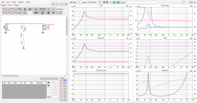
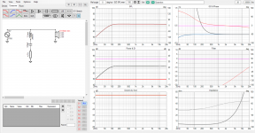
Here is circuit resistance in series with voice coil, its lowest ~4.7ohms, while it allows some damping current to flow its not as great as if there was ~0ohms circuit through amplifier output impedance.
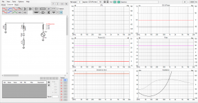
Without shunt, tadaa, no surprise impedance in seiries with voice coils is 270Ohms so not much damping current.
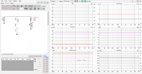
Last edited:
you mean "Pure current drive"?🙂 But who needs pure current drive?
All we want is to improve our systems, acoustic performance perceived by brain, right? Promise of current drive is reduced distortion, and where this reduction in distortion comes from? When you start to inspect it, you'll find out it comes from increased impedance in series with voice coil. This reduces distortion currents caused by driver motor, which directly reduces distortion measured acoustically. A very fine thing.
So, the current drive as such seems great but for example I don't see any value pursuing current drive by itself, by the sake of it. Neither does Joe to my knowledge, and perhaps anyone else. Value is in pursuing better system performance. Understanding where better system performance comes from one can tailor pieces available for a project, drivers and amps and passive components with enclosures, so that they can be arranged together as complete system with best performance.
I would reason that sometimes, if not always, some electrical damping would be nice. Also, our amplifiers are probably with low output impedance to readily accommodate this. So, what can we do? Calculate the impedance in series with voice coil and manipulate it suitably!🙂 We can have low impedance for the drivers resonance if we want, and high impedance below and above to reduce distortion, if we want.
Certainly, if someone has a current amplifier please use it, probably sounds very fine! Just manipulate box, perhaps choose differen driver, perhaps use passivenetwork, to tailor the frequency response right, and allow some damping current while doing it.
Last edited:
Yes you can do that!
Biggest caviat is: possibility to burn voice coil as accumulating heat does not affect circuit impedance (much at all) and reduce current / audible compression, which usually protects drivers burning. If its home application and you have plenty big drivers then no problem.
Current amplifiers are hard to make, (supposedly), for big current you need big voltage rails and stuff like that. Issues with stability or something. I'm not amplifier expert but you can read about it for example here https://sound-au.com/articles/current-drive.htm , basically the amplifier and speaker need to be tailored together. But, if and when you can do this I see no downsides for home hifi. Joes elsinore project has crossover that works with any amplifier output impedance.
Its matter if it is worth it for you. I'm not sure if one can hear the distortion in a good system anyway? I have no experience other than from my own system with some of the distortion reduction techniques applied and there doesn't seem to be much difference as I said before, I can measure reduced harmonic distortion but its not obvious when listening. It doesn't mean there wasn't any difference though, so you could just try it to find out if its something for you and for your system.
Simplest way to try it, is tadaa, add series resistor to your voltage amp. Something like 4-10ohms should already give some hint what happens. Probably the bass alignment changes, highs get boosted, and there is big difference. If you can compensate for these in DSP you'd hear better any real benefits.
class-D amp sounds like tube amplifier now?😀
Last edited:
- Home
- Amplifiers
- Solid State
- Current drive for Loudspeakers