Sure, basic circuit analysis. Kirchows stuff, more current flows where resistance (impedance) is lowest. Its all about circuit impedance. Shunt network between amp and driver, when tuned to drivers main resonance peak frequency, is parallel with the driver and has much lower impedance at that frequency than driver and thus most current in the circuit flows through the shunt and response is equalized.
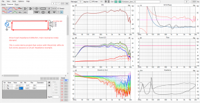
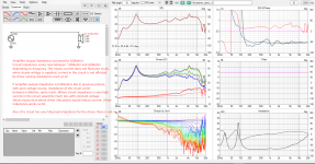

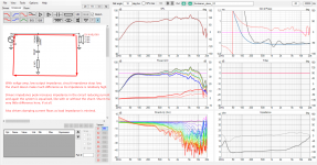
The same circuit can be also analyzed thinking about the drivers damping. You are right its not amplifier that does the (electrical) damping, its driver that does it by itself as long as there is low impedance circuit. When we have high output impedance on amplifier the damping current can flow through the notch. Amplifier damping factor is silly name, easy to misunderstand. We could also calculate damping factor for our passive filters and sell more speakers, I wonder why manufacturers are not utilizing this in marketing 😀
Here is example, high output impedance amplifier, tuning of the system Q just by altering impedance on the shunt, which determines how much current goes through the driver, and how much driver back-EMF makes damping.

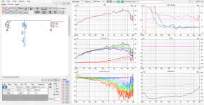
After all the amplifier does not have any say on what the driver + box Q is, only the circuit impedance as drivers load determines it. Amplifier is just part of the circuit and partially affects what the impedance is for the driver to make the Q.
ps. pardon the examples are from a demo project that ships with VituixCAD. The lower impedance peak of reflex box can be confusing, it would have been nice example with closed box measurements 🙂 Anyway, point is to demonstrate its the circuit impedance, not type of amplifier, that matters. We can manipulate circuit impedance for what ever we want, especially with active loudspeaker systems where any passive network can be tailored for impedance alone.


The same circuit can be also analyzed thinking about the drivers damping. You are right its not amplifier that does the (electrical) damping, its driver that does it by itself as long as there is low impedance circuit. When we have high output impedance on amplifier the damping current can flow through the notch. Amplifier damping factor is silly name, easy to misunderstand. We could also calculate damping factor for our passive filters and sell more speakers, I wonder why manufacturers are not utilizing this in marketing 😀
Here is example, high output impedance amplifier, tuning of the system Q just by altering impedance on the shunt, which determines how much current goes through the driver, and how much driver back-EMF makes damping.


After all the amplifier does not have any say on what the driver + box Q is, only the circuit impedance as drivers load determines it. Amplifier is just part of the circuit and partially affects what the impedance is for the driver to make the Q.
ps. pardon the examples are from a demo project that ships with VituixCAD. The lower impedance peak of reflex box can be confusing, it would have been nice example with closed box measurements 🙂 Anyway, point is to demonstrate its the circuit impedance, not type of amplifier, that matters. We can manipulate circuit impedance for what ever we want, especially with active loudspeaker systems where any passive network can be tailored for impedance alone.
Last edited:
Oops the first image is wrong, text missing, and already got off from computer. Here is some text that ought to be there. In the first image its just voltae amp and a driver in a (reflex box). Circuit impedance is determined mainly by the driver impedance. Its high on drivers resonance, and rising with voice coil inductance. Excursion would modulate and so on. Back-EMF voltage can make current in the cir uit, so driver is daped on the resonance. Response is flat because current decreases because impedanve is high, given cpnstant voltage.
Yeah sorry about the sloppy example images, I could have drawn the orange back-EMF current into the first image as well, and draw it circulating opposing direction and so on, light red current through the driver with the shunt in place and so on 🙂
Anyway, VituixCAD is nice to experiment with this as it shows acoustic response. Acoustic frequency response is directly related to current through voice coil.
However, VituixCAD examples do not show distortion which is the main motivation for current drive. Above example touched on driver resonance damping but not distortion. Distortion can also be examined with the impedance with the examples above but requires some imagination to augment the graphs. Few examples below to help imagining how impedance in the circuit affects the distortion in acoustic domain. Please refer to Esa's article in EDN when in doubt.
In short, distortion performance we measure acoustically is affected by many things. "current drive", or circuit impedance, is concept in electrical domain and affects acoustic distortion through non-linear effects in the circuit impedance for example, and as extra voltage source in the circuit, both of which happens when voice coil moves.
What happens in the electrical domain needs to appear as current through voice coil in order to turn into acoustical domain. If anomaly in electrical domain does not appear as current in the voice coil it does not turn into acoustic domain ( or less so ). This is the key, simplified, manipulating circuit impedance seen by the driver we manipulate the current generated and affected by the driver: high impedance, less influence on circuit current, less distortion.
Driver motor back-EMF appears series voltage source in the circuit and can make current into the circuit over the circuit impedance. When impedance in the circuit is low the back-EMF generated current flowing in the circuit, and through voice coil, is relatively high and appears into acoustic domain as distortion at the very moment. Same thing if driver impedance changes with excursion also circuit impedance changes with excursion, which would affect any current flowing in the circuit and appear as distortion in acoustic domain at the very moment. Unless, circuit impedance is high so that driver portion of the impedance fluctuation stays small. When circuit impedance is increased both of these effects to current are reduced, fluctuation of the circuit impedance and current generated by back-EMF.
Impedance is frequency dependent. Take for example the Le(x), inductance of the voice coil which varies with voice coil position in the magnetic gap. When circuit impedance is low, like with voltage amplifier hooked with short cables directly to the driver, then variation of this inductance makes variation of the circuit impedance on high frequencies (few octaves above driver resonance and up) and some current (distortion) appears into the circuit, which is measured as distortion in acoustic domain. Imagine low frequency sound making big excursion, which means big variation in Le(x) which mainly affects circuit impedance at high frequencies. In effect, low frequencies make high frequencies distort. Well, this is only one distortion mechanisms and in modern drivers seems to be quite small. Many drivers have Le(x) within ~0.05mH or so with few mm excursion, for example this one https://audioxpress.com/article/test-bench-faital-pro-6rs140-midwoofer-midrange or this one with crazy low ~0.005mH https://audioxpress.com/article/test-bench-purifi-audio-s-ptt5-25x04-nfa-01-midbass-woofer
And there is more, like the microphone effect. For example mode inside our box makes pressure affecting the cone from outside, the driver microphones the box mode into electrical domain, back-EMF voltage appears. On high frequencies back-EMF phase can be past 90 degrees even boosting microphoned sounds some, unless impedance in the circuit is high reducing the current. Even if it didn't turn directly into acoustic domain like this the cone would move (some) and change drivers electrical parameters for the sound it is producing. Effect of this would diminish when circuit impedance is high.
Well, anyway, these can be quite minor effects on good drivers, but perhaps major effect on some systems like some full-range drivers. And none of it has anything to do with amplifier other than its output impedance.
This knowledge of reducing driver motor generated / affected current works as distortion reduction mechanism can now be exploited quite easily on all kinds of systems. No matter current or voltage drive we can affect circuit impedance with passive parts. All we have to do is think what the impedance seen by the driver is and manipulate it. Of course some constrains are laid as we need to consider also impedance for amplifier load, what the frequency, how much amplfier current flows through driver, what the frequency response is.
Purifi has excellent example of parallel notch filter in series with a woofer to reduce (distortion) currents in electrical domain, which the cone resonance would amplify. Same EQ notch to equalize the cone resonance could be done with series filter, but it would not reduce distortion currents in the circuit.
https://purifi-audio.com/wp-content/uploads/2022/03/220211_R05-Notchfilter.pdf
Sorry, bit of a monolog but few more examples.
Found out VituixCAD enclosure tool can export simulated closed box SPL and impedance plots. Lets try something. These are examples with voltage amplifier, but they demonstrates what we can do by knowledge on how circuit impedance affects things.
Here is sloppy bass box, not very low frequency extension but fine as an example. Hooked to a class-D amp, not much impedance in the circuit apart from the driver itself so the driver back-EMF dampens itself at resonance. Box is dimensioned and damped so that system Q is nice in combination of the two, mechanical and electrical damping.
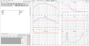
But, now the speakers are dragged on to the roof for garden party, long speaker cables. Resistance in the cabling appears increases impedance in the circuit and electrical damping of the driver is reduced. Back-EMF voltage makes less current in the circuit, driver resonates with less damping in the system, system Q has increased and we have a peak in the response.
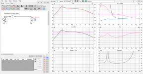
But hey, we can just add low impedance circuit inside the bass box, with short wires, to allow damping current to flow! Nice, although expensive 🙂
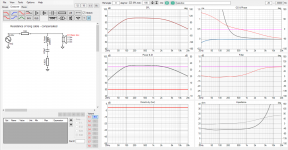
Ok, another example. What if we wanted the peak? What if we want to extend such box response by allowing the driver resonate some, reduce electrical damping, increase impedance in the circuit a bit? For sure, simplest is to increase the circuit impedance on low frequencies with a capacitor.
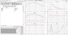
These are some practical examples how to utilize circuit impedance. These are for bass box, purifi example linked on previous post was for ~mids, woofers top bandwidth distortion reduction. How about tweeters then?
Here is two different ways to make a pad and simple high pass filter for a compression driver. Whats the difference, which one would reduce the horn to microphone bass and mids and possibly reduce distortion due to reducing the driver dome movement due to this external pressure affecting it?
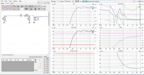
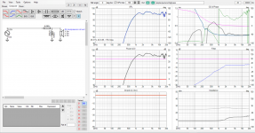
Well, propably not too big of a difference in practice, not sure if I hear any. Anyway an example that a desired frequency response can be attained in various networks and the difference would be in impedance seen by the driver, which affects damping current and distortion currents.
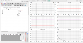
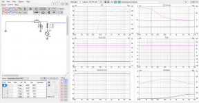
On these above graphs all impedance plots show load impedance for the amplifier. To analyze what impedance there is outside the driver as drivers load, use trick from the Purifi paper, swap the source in place of the driver to see the impedance, short the driver if wish to see only what the passive network adds / does. Here few from the above
Found out VituixCAD enclosure tool can export simulated closed box SPL and impedance plots. Lets try something. These are examples with voltage amplifier, but they demonstrates what we can do by knowledge on how circuit impedance affects things.
Here is sloppy bass box, not very low frequency extension but fine as an example. Hooked to a class-D amp, not much impedance in the circuit apart from the driver itself so the driver back-EMF dampens itself at resonance. Box is dimensioned and damped so that system Q is nice in combination of the two, mechanical and electrical damping.

But, now the speakers are dragged on to the roof for garden party, long speaker cables. Resistance in the cabling appears increases impedance in the circuit and electrical damping of the driver is reduced. Back-EMF voltage makes less current in the circuit, driver resonates with less damping in the system, system Q has increased and we have a peak in the response.

But hey, we can just add low impedance circuit inside the bass box, with short wires, to allow damping current to flow! Nice, although expensive 🙂

Ok, another example. What if we wanted the peak? What if we want to extend such box response by allowing the driver resonate some, reduce electrical damping, increase impedance in the circuit a bit? For sure, simplest is to increase the circuit impedance on low frequencies with a capacitor.

These are some practical examples how to utilize circuit impedance. These are for bass box, purifi example linked on previous post was for ~mids, woofers top bandwidth distortion reduction. How about tweeters then?
Here is two different ways to make a pad and simple high pass filter for a compression driver. Whats the difference, which one would reduce the horn to microphone bass and mids and possibly reduce distortion due to reducing the driver dome movement due to this external pressure affecting it?


Well, propably not too big of a difference in practice, not sure if I hear any. Anyway an example that a desired frequency response can be attained in various networks and the difference would be in impedance seen by the driver, which affects damping current and distortion currents.
On these above graphs all impedance plots show load impedance for the amplifier. To analyze what impedance there is outside the driver as drivers load, use trick from the Purifi paper, swap the source in place of the driver to see the impedance, short the driver if wish to see only what the passive network adds / does. Here few from the above


Last edited:
Thats all, sorry bit of a burst of output.
Hopefully most of questions anyone would have get answered by reading it again 😀
To summarize, current through voice coil makes into acoustic sound. Key is to understand what the current is composed of and how to affect it and the answer is circuit impedance seen by the driver. High impedance seen by the driver (series with the driver) reduces drivers effect on the current in the circuit. Low impedance at drivers main resonance has useful effect as enabling driver dampen itself electronically, otherwise its just enabling distortion to appear into acoustic domain. Both voltage and current amps will do fine and can achieve similar effects on various applications if we use passive components to manipulate impedance in the circuit.
I've tried some of the stuff in my own home stereo system, but I'm not sure if I hear any difference. Need to do some blind listening tests when the system is finished, some rainy weekend in the future. Its a multiway system with pro drivers with all sorts of tricks on the motors and small excursion in general, probably contains more audible issues than what these tricks would solve. Perhaps some other system would show more audible differences.
I'm quite sure there is some errors in the posts, terms and such, but this is the simplest way to understand whats happening and utilize the understanding in real applications without too much math and voodoo. Hope it helps everyone to get handle on the subject!🙂
Last edited:
I think that I am going to need a couple of days to read that... 😎
Just kidding, will try to summarise a bit later.
Just a thought, KSTR has nothing 'new' to offer, whatever 'new' is?
This thread is about current because the source is current drive.
Understanding the force-factor relationship with the current, the theory is not 'new' but the understanding is meager. And it is no wonder, because 'thinking' current is much harder than thinking 'voltage.'
This is not about what we 'know' in a technical sense, this is about what we 'understand' is happening. And that is far more nuanced than most people seem to understand, so they go around in circles. The fundamental understanding between damping and current is largely misunderstood. There is data out there, nobody is doubting that. But what does it actually mean?
You have to have an appetite to find out. For sure KSTR does not have one, he is already filled.
This thread came back to life because I remembered it. Will it go dormant again?
There are many reasons not to use current drive for speakers. The first and foremost is the speaker designers development and testing methodology.
This also brings us back to current feedback amplifiers and whether or not, the term is marketing hype. I guess in the end for audio the clipping behaviour is what differentiates CFA and VFA. So VFA could be the daddy of CFA
Drive impedance determines electrical damping
No!
It only appears this way.
Dig deeper and it is the varying current with frequency that determines the electrical damping.
And since you claim to know with a capital 'DO' then you should know because it's physics.
There are many reasons not to use current drive for speakers. The first and foremost is the speaker designers development and testing methodology.
I agree with the first part, and as always I have to point out that I am far more in the 'voltage' camp. The world is not going to get converted to current drive. Also, those who insist on using current drive should come to grips that they don't know how to use it on the bass. It is the position taken by KSTR that is the reason.
The second point you mention is far more difficult. Take software like SoundEasy which is widely used to model crossovers (I use it) and it is all based on the voltage mode. But when it comes to dynamic loudspeaker, the crossovers are current dividers. The fact that the seem to be voltage dividers can be a useful tool, but it would be an even better tool if we kept the look at what is happening on the current side. But how many speaker designers are doing that?
It's the same thing.
It depends on what 'it' is and how is 'it' the same thing. I absolutely state that the output impedance is not the determining factor here. You can have as much damping you like with any high impedance, indeed even if it was a theoretical infinitive. How? You have to look at the current. It's counter-intuitive I know, but unless you look there you cannot have a more complete picture.
Both maths and physics support this. It just not being considered. It's about not looking.
What do you mean?'thinking' current is much harder than thinking 'voltage.'
Yes, of course, trivially so. The driver does not know about the source impedance. When its terminal voltage (or current) is the same the output is the same, obviously. But, as mentioned, the fine print is different (distortion and error recovery).
Not trivial
The amplifier does not 'see' its own output impedance. Indeed at any one frequency, the amplifier can only see one impedance. If the amplifier 'sees' at 1000Hz an impedance of 9 Ohm, does it know what its own output impedance is?
Here are a two not so trivial points:
A. A perfect voltage source will have zero output impedance and have no control over the current.
B. A perfect current source will have an infinite output impedance and have no control over the voltage.
Now please don't give a tricky answer, I have seen it all before, so I have to now qualify what I said by adding one word:
A. A perfect voltage source will have zero output impedance and have no direct control over the current.
B. A perfect current source will have an infinite output impedance and have no direct control over the voltage.
Now please don't take it out of context.
And if you trivialise these two points, then why are you here on this thread? Please don't try shut down the conversation or this thread will go silent again.
What do you mean?
"Thinking voltage is easy, thinking current is hard."
I was quoting Menno Vanderveen. Maybe you know who that is?
Indeed I put it to him directly in person at the European Triode Festival in November 2018 (ETF18), that we are listening to the current of the amplifier and not its voltage. He did not blink. In fact he said that the good thing is that we should work out a way of proving it. The mere fact that there is a challenge in that it needs to be proven. Shouldn't be obvious? But no, it should be obvious and yet it isn't.
F = Bli
Should that be proof enough?
The Force is B in Testla, l is the length of the voice call within the gap (the rest of the VC not part of it) and i is the current.
No voltage there.
So if we have a 'voltage' answer, then it cannot be the complete answer. So the electrical Q of a system must have a current based answer as well. But just as impedance is the inverse of current, or should I say the other way round? Logic tells us the varying current versus frequency should give us the more complete answer when F=Bli.
It is strange, but even when people are discussing current they slip back into talking voltage. And it is done almost unconsciously. I think this is arguably the toughest topic in all audio. There is a definite mental block and it['s because voltage is easy, current is damn hard. It's one of the reasons that there are endless discussion about so-called current drive, but they soon get nowhere. You literally have to think a different way.
Since that discussion with Menno, I have been at work at this aspect of proving and I believe I have come up with a series of scenarios where the other person can only give the correct answer. This helps them overcoming the problems.
The irony in all this is that there is nothing wrong with the physics, and nothing wrong with the maths, the problem is inside our own heads.
This is the damnedest thing.
Returning to the issue of excess inductance outside of the magnetic gap: it may only dominate at high frequencies, but that doesn't mean it drops to zero in the bass. Using CAD modelling when designing the magnet may help to keep the field symmetric, so that overhanging parts cancel out. But that still doesn't fix dynamic effects with the coil moving around, or with variable saturation depending on signal strength.
One other effect I've encountered is that a theoretically well-damped speaker could activate room resonances moreso than if it's "detuned" by a raised output impedance. This probably won't affect everyone, as it would depend on the listening room and how lossy the walls are for instance. A "knuckle test" on a short-circuited speaker cone just isn't enough activate audible room modes, which may be why this test gives the illusion of a cleaner result when the speaker is shorted. It's easy to forget that one woofer cone can constrain the air in two boxes, and ultimately the air pressure inside the bigger box is only indirectly related to the cone position.
One other effect I've encountered is that a theoretically well-damped speaker could activate room resonances moreso than if it's "detuned" by a raised output impedance. This probably won't affect everyone, as it would depend on the listening room and how lossy the walls are for instance. A "knuckle test" on a short-circuited speaker cone just isn't enough activate audible room modes, which may be why this test gives the illusion of a cleaner result when the speaker is shorted. It's easy to forget that one woofer cone can constrain the air in two boxes, and ultimately the air pressure inside the bigger box is only indirectly related to the cone position.
Does it make any sense to use current drive on magnetostats ? The impedance is usually ruler flat, because there is no (or little) coil inductance or electromagnetic resonance.
@tmuikku I admire your passionate posts 🙂
In Xsim, one can chose to view driver lookback impedance, which is nice to visualize the level of current drive in a passive XO, I wish that would be implemented in vcad too.
But it is not really about passion. In fact you have to think very dispassionately.
The interface between the amplifier and the dynamic loudspeaker, is the most complex interface of all, in all the various stages in audio. Nothing comes close. Maybe the room does too, but here we are talking about the electrical chain.
The key to make crossovers work in current drive is actually very simple. EQ the current, and it works equally well with both current drive and current drive. It fixes some things that are common to both, and some things that are different in each. The frequency response stays the same, no matter what the source impedance is, high under current drive and low under voltage drive.
When you EQ the current, the drivers gets the same current at any and all frequencies. Even the bass alignment stays put. You will also have the same damping because the alignment has not changed.
Current EQ makes current drive at least practicable. BTW I have a 40 Watt Transconductance (current out) amplifier with 270R output impedance, so I am not just talking theory. This stuff actually works and if anybody does not believe me, the front door is open. I can demonstrate it to any disbelievers.
Here is example:
Here is how one example with well picked drivers worked:
Take this as a sealed box, with vented box it is a bit more tricky, but is does work:
But there are additional hidden benefits. A current source is much more immune to impedance modulations that is caused by the back-EMF impedance of the driver not being stable. With current drive, by fixing (virtually regulating) the current, impedance modulations that normally cause current modulations, are suppressed. This is the advantage of current drive. But current EQ applied in the right way with conventional amplifiers (voltage), also suppress current modulations and hence you get a sound that is much more similar to current drive than voltage drive. At the critically mid-frequencies, with EQ, most of the current goes through the 0.2mH/33uF/6R8 and pulls the current phase angle of the amplifier to zero. Since the current modualtions of the amplifier is happening at a much lower current level, and now becomes a smaller part of a now much more current from the amplifier, this means you have a mechanism that gives you similar advantage to current drive and none of the disadvantages.
But I still favour voltage amps for a simple reason: The world is not going to be converted to current drive - and you don't need to.
I am only giving you the tip of the iceberg.
Does it make any sense to use current drive on magnetostats ? The impedance is usually ruler flat, because there is no (or little) coil inductance or electromagnetic resonance.
Absolutely. Just ask Nelson Pass.
I am not pro current drive because I believe the same advantages are available via voltage drive. Manipulate the current with voltage drive, and you can have success.
But ribbon speakers with that flat impedance? In an active system, it makes very good sense to use current drive.
- Home
- Amplifiers
- Solid State
- Current drive for Loudspeakers