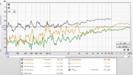
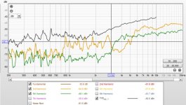
I've experimented with current drive and have seen improved acoustic distortion results over voltage drive in certain applications. Most recently using DML's (Distributed Mode Loudspeaker) with a single exciter (supplemented by separate enclosed woofers below 250Hz). I have found the acoustic distortion to be at least 5dB less above 3kHz using a current drive amp (compared to a voltage drive amp). See attached SPL chart, orange is current drive and blue is Hypex Ncore (voltage drive). Notice the "natural" EQ with current drive above 12kHz as the exciter's impedance rises. The second chart is the current drive distortion and the third chart is the Hypex Ncore distortion. The distortion reduction with current drive is most noticeable in the odd-ordered harmonics.
Thanks,
Dave
Thanks,
Dave
Attachments

Current drive means no electrical damping of unwanted cone movement. You have to do it all mechanically somehow.
Common misconception, quite understandable, But not quite. If you can find a way to effectively cancel the output impedance of the amplifier, then no electrical damping is lost when using a current source, and you don't have to rely on mechanical damping. This is not theory, it has been done. I have mentioned this at various times on the 'Elsinore Project' thread. The Elsinore from Mk5 onward can be equally effectively driven by both voltage sources and current sources.
Current amp output impedance is very high so damping current from driver back-EMF cannot flow through there. One can put shunt network on the circuit that allow low impedance between driver terminals, this enables back-EMF of driver to generate current to flow and the driver dampens its own resonance, the current opposes the movement of the voice coil / cone.
For example, on a compression driver, instead of using series capacitor as high pass with L-pad for attenuation one can use series resistor and shunt inductor. This will act as high pass filter but also makes very low impedance for the driver load, which enables current from back-EMF to flow which takes care of the damping. Resonance of the driver doesn't show up in frequency response measurement when with series capacitor it usually does.
Woofers might not require high pass filters or attenuation, so one could make series notch (that is in parallel with) the driver. This works as notch filter for the driver resonance resulting frequency response peak because some amplifier current flows through it, but it also provides lower impedance path for driver back-EMF generated current to flow enabling damping. Need to make VituixCAD example of this at some point.
How could i have missed this thread? One of the most obvious yet overlooked sound-improving tricks that I've seen (or heard rather) is the routine use of L-pads to reduce the excess "sensitivity" of tweeters.
Hardly anyone seems to notice that at least part of the improvement can be attributed to a reduction of distortion. A 1-5 or so dB change in sensitivity ought be a benign change in "heat", like changing the listening position by moving out of the on-axis beam. Instead, a clear change in the quality of the sound can also be experienced.
I also wonder if this is also why so many people seem to get mixed results with active filters vs passive. Active filters ought to be a slam dunk with superior technical performance and reduced amplifier distortion before the speakers factor into the equation. But if the tweeters are EQed at line level, you lose the benefit of raised output resistance.
Exacto, just use mixed topology if you want to. Perhaps there is not much difference always since drivers can be rather good, but sometimes might be. Like series inductor with actively driven woofers to allow damping current flow on woofers resonance but then reduce motor related non-linear distortion higher up, at drivers resonance. Or the purifi parallel notch (in series) to raise impedance on cone resonance to reduce distortion current there, perhaps best use to really pump up the impedance.
ps. there is also more recent thread on the subject https://www.diyaudio.com/community/threads/help-to-understand-current-drive.390405/
ps. there is also more recent thread on the subject https://www.diyaudio.com/community/threads/help-to-understand-current-drive.390405/
Last edited:
Unwanted cone movement at resonance? Not big deal. Simple filter will do the job.Current drive means no electrical damping of unwanted cone movement. You have to do it all mechanically somehow.
Damping is an interesting concept. A conventional audio power amp forces voltage whereas an ideal current source forces current. If you look at an oscilloscope capture of voltage and current of a low frequency large signal sine wave driving a woofer to large excursion, the voltage waveform is nice and clean while the current signal is very distorted. The current is what drives the motion of the cone. A current source forces current and the distortion caused by the woofer winds up in the voltage waveform. Somewhere I have a scope shot of the current and voltage signals of a woofer under large excursion with a conventional audio amp. I will have see if I can dig up that waveform capture.
Don’t be excited to see current distorted under voltage drive. Current drives the loudspeaker, but especially at high excursion is worse than voltage usually. Magnetic field is likely way off at high excursions and stiffness is definitely very non linear. These non linearities are partialy compensated by voltage drive. At higher frequencies lower excursions other nonlinearities starts to dominate and that is where current drive helps.
Anyway both drive methods are not perfect, just both have advantages over another regarding the origin of distortion.
Anyway both drive methods are not perfect, just both have advantages over another regarding the origin of distortion.
In my own experiments, I've found that a slightly raised output resistance actually seems to tighten up one-note bass. At first I was confused by this. I expected the worst after reading multiple reports of loose flabby bass, and also because most box modelling programs show a nice smooth response with no output peak whatsoever in spite of impedance peaks, which could be an error in the theory somewhere.
E.g. add 22 ohms in series with a typical voltage amplifier and 8 ohm speaker with 30 ohm peak.
(30+22) / (8+22) will give a lower Q than 30 / 8. I verified this by applying notches to flatten unwanted peaks, and the raised impedance version required less dB of correction and lower Q.
A couple of things I want to try out:
1) Modifying the current-sense feedback loop in a transconductance amplifier to include a Linkwitz transform or twin-T notch, inverted so it becomes a band-boost in the bass resonance area.
2) Compare that with mixed feedback. The amplifier has voltage feedback based on an RC filter. Instead of the NFB signal being grounded at HF, it is connected to the current sense resistor, so there is a smooth transition from voltage feedback at LF to current sensing feedback at HF.
3) A 3rd option would be a dedicated EQ in a pre-amp / active filter stage before the power amp.
Anyway both drive methods are not perfect, just both have advantages over another regarding the origin of distortion.
This point intrigues me. Please read on, I think I may have a surprise for you.
To start with, I am far more interested in getting voltage drive right as I have said many times, the world is not going to get converted to current drive.
Yet there are things we can learn if we study current drive and then apply a better overall understanding of what the current does and improve voltage drive. How revolutionary is that? 🙄
Thinking in terms of current is very hard on the brain cells. Often the things we have been led to believe don't pan out. At this point many just stop and revert to 'traditional' thinking and we don't get much progress. The brain is a funny thing, we get to think in cycles and then it is hard to break out of them.
I have adopted a view that both 'drives' are not really so much drives, they are simply different ways of delivering current - we should look upon all amplifiers as current-delivery-systems when it comes to dynamic drivers. Also, we need to finally get something straight, that we are not listening to the voltage of the amplifier and only the current (yes, that will be a leap for some). Look at what the current of the amplifiers does, don't take your eyes of it, it is what you are listening to.
Here is something to think about:
1. Take a voltage source and connect it up to a speaker with 50 Hertz sine wave. You will hear the 50 Hertz tone. Now with an AC current meter in series, adjust the amplifier so that you see a current, let us say 500mA as a round number. Now set up a microphone at around 10cm. If all is right, you should see a fairly clean sine wave and project on a scope as channel 1.
2. Take a current source and connect it up to a speaker with 50 Hertz sine wave. You will hear the 50 Hertz tone. Now with an AC current meter in series, adjust the amplifier so that you see a current, again the same 500mA as a round number. Now set up a microphone at around 10cm. If all is right, you should see a fairly clean sine wave and project on a scope as channel 2.
Both will now be on the scope and indeed they will look the same.
Even with the current source there will be no overshoot even if we see large excursions. As they are the same, and this will again be a stretch for some, the damping will be the same. It took me a long time to wrap my head around that.
In both cases we are listening to the current of the amplifiers and that is 500mA in both cases. Current is the only true force-factor involved.
Also, the current source will be just as clean as the voltage source. You could do distortion measurements and compare.
I hope the above does intrigue you, and interested in hearing positive comments.
But anybody, not just you, please avoid being disparaging or dismissive. The beginning of this thread said:
In this thread we will discuss current vs voltage drive of loudspeakers in an open and friendly way.
Hear, hear!

Once again, on another thread, I have gotten the same reaction that I have now seen over and over again over many years.
I talk about current in speakers and nobody understands me because they think that I am pro-current drive.
I want to put it on record that I am pro-voltage drive.
OK?
What I want to see is better sound and lower distortion with voltage drive by understanding better what the current does.
If anybody reads my posts thinking that I am pro-current drive, then there is a good chance that they won't understand much of it at all.
C'est la vie.
.
On a scope it's usually hard to detect low level distortions visually due to the linear scale. Changing it to a log scale ties in with frequency conversion.
The ear is pretty insensitive to bass, but has a good dynamic range, so it should be possible to make a test rig with a potentiometer or something that's easily adjustable like that, where the output resistance is adjusted and the overall gain automatically compensated at the same time. Then listen for any practical differences.
The ear is pretty insensitive to bass, but has a good dynamic range, so it should be possible to make a test rig with a potentiometer or something that's easily adjustable like that, where the output resistance is adjusted and the overall gain automatically compensated at the same time. Then listen for any practical differences.
Yep! That's true about bass distortion sensitivity. There is a blog on the Purifi website about that. But what I was highlighting is that IF the current is the same, the sound pressure level will be same. And the damping will be the same. The current source will not have less damping, there won't be any overshoot that is left uncorrected. There is something unexpected happening, but not unexpectant when we figure out what the mechanism is. Then it becomes obvious.
Low frequency are not necessarily less damped under current drive. That what the example shows. If using a single frequency and matching the current, there will be no lack of damping. If we must match the damping of voltage drive with current drive, we can apply EQ, so that at any one bass frequency we might pick randomly, the current will be the same and hence the Q of the system will be the same. This can definitely be exploited in a couple of ways, for some who want to insist on current drive. But that is not me, as I am about getting voltage drive right (lower distortion, not just in the bass).
Low frequency are not necessarily less damped under current drive. That what the example shows. If using a single frequency and matching the current, there will be no lack of damping. If we must match the damping of voltage drive with current drive, we can apply EQ, so that at any one bass frequency we might pick randomly, the current will be the same and hence the Q of the system will be the same. This can definitely be exploited in a couple of ways, for some who want to insist on current drive. But that is not me, as I am about getting voltage drive right (lower distortion, not just in the bass).
Hi Joe,
I hope we can get to same page with it 😀 I'll try write your example open with enough accuracy.
If we use same speaker driven with either current source or voltage source, and adjusting for same current for both on a frequency near system resonance, any difference with the two different systems damping would appear when signal was cut off, wouldn't it?
Current source connected directly to a driver makes high impedance circuit, while voltage source in place makes low impedance circuit. If circuit impedance is high, the cone would be damped only mechanically before coming into rest after signal cut off. If circuit impedance is low, also some electrical damping happens. So, I think in this case the system with current source will have less damping around drivers main resonance, because less current flow with back-EMF. Unless there is low impedance path around the amplifier, crossover shunt network.
On some higher frequency the damping for both systems would be the same, as electrical damping does not realize due to phase lag in back-EMF generated current. Esa's article shows math for this if anyone is interested checking out why.
Lets get back to the bass frequency near driver resonance:
If there was shunt as EQ in the current source case to equalize system responses alike at the system resonance, then there would be low impedance path for electrical damping current and damping would be ~similar on both cases.
If system frequency response EQ was done with DSP instead of a shunt circuit between amplifier and driver, there would again be less damping with current source due to high impedance. Systems steady state frequency responses would be the same though.
Both systems can be made "mixed drive": Current source with shunt circuit tuned to driver resonance, or voltage source with series inductor (as part of multiway system low pass filter) would both make similar system. Both would have low circuit impedance at woofers main resonance to enable damping current, and higher impedance higher up in frequency to reduce back-EMF distortion current.
I would encourage people to have a look at the motor design of most speakers. Specifically, the voice coil height vs the height of the magnetic gap, and the materials that the magnet is made of. And also try to break the 'gross' voltage down to smaller increments along the length of the coil.
So, for a given voltage signal, there will be some voltages at the top of the VC, some in the middle where most of the mechanical forces are produced, and some at the other end. As long as the voltages are spread evenly, everything should be fine: the fraction of the VC that is located in the gap is like 2 auto-transformer taps whose voltage is a steady fraction of the total voltage applied at both ends, right?
But as we apply more detail to the inductor, we find that the incremental inductance is not the same along the length of the coil. The iron core interacts with the coil, giving it more inductance in some places than others. This means that for a VC divided into 3 equal lengths, the inductance will be different for each. What's worse, it will change dynamically as well when the coil moves around. The deflection of field lines in the core will also have an effect, so there could be a range of different inductance curves for the same mechanical position depending on the signal strength. So the voltage (and current) across the sound-producing part in the middle will be modulated by the excess inductance of the overhanging parts.
If we could run a couple of taps off the VC to measure those inner voltages, we could see that they vary in spite of a voltage amplifier's best efforts. The trick with so-called current sensing is that the current through the sense resistor is (likely) a much better approximation of the current in the middle of the coil.
Some speakers try to improve on this state of affairs by short-circuiting the over-hanging inductance with copper loops. This ought to make the inductance more consistent along the whole length of the coil, so it acts more like it's underhung. But it still seems like a stop-gap measure, and probably introduces other problems like parallel paths for the current to go through, in which case it's not measurable with just a simple resistor.
Last edited:
Edit #2, actually I'm not entirely sure about the last part about adding copper around the VC. It seems like electrons in the secondary winding get pulled in the same direction as in the primary, and the field lines partly cancel out, reducing the overhanging inductance. But in doing so, there is a braking force (Qms goes down), which could also be prone to modulation.
Perhaps you're considering a clip of the steady state response?1. Take a voltage source and connect it up to a speaker with 50 Hertz sine wave. You will hear the 50 Hertz tone. Now with an AC current meter in series, adjust the amplifier so that you see a current, let us say 500mA as a round number. Now set up a microphone at around 10cm. If all is right, you should see a fairly clean sine wave and project on a scope as channel 1.
2. Take a current source and connect it up to a speaker with 50 Hertz sine wave. You will hear the 50 Hertz tone. Now with an AC current meter in series, adjust the amplifier so that you see a current, again the same 500mA as a round number. Now set up a microphone at around 10cm. If all is right, you should see a fairly clean sine wave and project on a scope as channel 2.
Both will now be on the scope and indeed they will look the same.
Perhaps you're considering a clip of the steady state response?
[I am learning 'Quote' thingy and it is working for me. 👍👍]
You mean a clip as a screen shot of the scope? If so, I don't have it set up right now, but I should be able to do that in the near future.
I would encourage people to have a look at the motor design of most speakers. Specifically, the voice coil height vs the height of the magnetic gap, and the materials that the magnet is made of. And also try to break the 'gross' voltage down to smaller increments along the length of the coil.
Oh, this is a wonderful topic. I would like a discussion on this very much. There is something that is hidden in open sight there and it is delicious.
On average, only around 30% of the length of the VC is in the gap. The inductance we measure across the entrire voice, pretty much is only developed in that gap, only that part of the VC.
I think that it is OK to model the VC as if it was a single layer. For simplicity's sake. There is good precedence for doing so, as we model the inductance as a lump is series with the DC resistance of the VC and also the motional impedance.
[Apologies to Esa Merilained, Red added.]
It makes it easier going forward, but I do have some interesting things to say.
Cheers, Joe
Put another way.. perhaps you're not looking at the start or finish of the waveform?Both will now be on the scope and indeed they will look the same.
- Home
- Amplifiers
- Solid State
- Current drive for Loudspeakers