No, check out this URL:
Impedance Compensation
If one have frequency independent 8 ohms (or 4 ohms), that means even an equalizing around fo of the bass transducer, what difference remains in this case between voltage drive and current drive ?
What audible differences remain at a listening test between both modes with perfect impedance equalizing of the whole speaker system ?
In that case voltage drive vs current drive is the same in linear part of system transfer function. But non linear part is different voltage vs current. In other words the same except distortions. 😉
Listening differences depends on loudspeakers a lot.
seems someone else did achieve a good step on this:
Why current-drive? - An active current-drive audio systemAn active current-drive audio system
Thank you!
Damping and low QTS are essential
Yes. Convert the speakers to aperiodic, or if that is impossible for some reason, design and build aperiodic speakers. Low QTS for driver(s) is recommended.
There are many ways to approach sufficient damping. Heavy damping material is one, such as cotton fabric. Acoustic resistance (such as Variovent) is another. A damped acoustic labyrinth is third possibility, and it does not require special damping materials, because cheap polyester wool is sufficient as the labyrinth becomes long enough.
Once you have achieved sufficient damping, there you have it.
Current drive means no electrical damping of unwanted cone movement. You have to do it all mechanically somehow.
Yes. Convert the speakers to aperiodic, or if that is impossible for some reason, design and build aperiodic speakers. Low QTS for driver(s) is recommended.
There are many ways to approach sufficient damping. Heavy damping material is one, such as cotton fabric. Acoustic resistance (such as Variovent) is another. A damped acoustic labyrinth is third possibility, and it does not require special damping materials, because cheap polyester wool is sufficient as the labyrinth becomes long enough.
Once you have achieved sufficient damping, there you have it.
Not the same thing.
Aperiodic has little to do with Q. You are trying to flatten the impedance resonance. It is aperiodic if there is no bump. Hard to get all the way there.
A current amplifier provides little or no electrical damping to the loudspeaker so the Qm. If you use an amplifier with infinite Rout and the driver in an infinite enclosure the low frequency response will have box Q the same as the mechanical Q.
So if you can find a driver with Qm 0.707 then you can get close to that in a large enuff box.
In practical terms we can find driver swith Qm as low as 1.3, 1.4. Say up to Qm = 2. The driver will be peaky in a sealed box. Aperiodic damping is an attempt to lower this — ie add more mechanical damping to the driver.
dave
Hi all, I have recently realized various materials don't have constant acoustic absorption over frequency but in general the absorption is very low at low frequencies and ramps up on the upper bass or low mids on many materials. Thick layer of glass wool for example, seems to have relatively high absorption coefficient already at low frequencies, can be around 0,5 at ~100Hz which corresponds to 6dB attenuation but rock wool in similar thickness seems to be much less on the low frequencies. A table https://www.acoustic.ua/st/web_absorption_data_eng.pdf showing absorption coefficients on various materials.
I guess the material has to be right kind to have effect on the resonance which often is at very low frequency <100Hz? Anybody has info how compression of the material affects this the coefficient in the low frequencies, makes it higher? How much absorption would be effective to dampen the resonance of driver "enough"? 1dB, 3dB, 6dB more, any idea, anybody done some measurements?🙂
I guess the material has to be right kind to have effect on the resonance which often is at very low frequency <100Hz? Anybody has info how compression of the material affects this the coefficient in the low frequencies, makes it higher? How much absorption would be effective to dampen the resonance of driver "enough"? 1dB, 3dB, 6dB more, any idea, anybody done some measurements?🙂
Last edited:
Hi all, I have recently realized various materials don't have constant acoustic absorption over frequency but in general the absorption is very low at low frequencies and ramps up on the upper bass or low mids on many materials.
Ignore the bradbury parts (they have been shown to be in error) but the realworld charts of material damping effectiveness vrs frequency is shown near the bottom,
Bradbury's Fiber Equations
dave
A current drive can readily be experienced by using a normal large power amplifier which produces an output voltage. Connect a passive resistance that is about ten times or more a speaker's impedance in series with the speaker. The result will be a current that is proportional to the output voltage as the speaker's impedance would be minimal. This is a current drive, although extremely inefficient.
The experiment can be repeated while increasing the series passive resistance. If there are sound reproduction differences between voltage drive and current drive, they should be noticeable. Use a two channel amplifier with one channel having the resistance and the other with the speaker normally connected but with the volume set to produce 10% of the output of the other channel. Switching from one channel to the other one can compare the sound reproduction easily.
The experiment can be repeated while increasing the series passive resistance. If there are sound reproduction differences between voltage drive and current drive, they should be noticeable. Use a two channel amplifier with one channel having the resistance and the other with the speaker normally connected but with the volume set to produce 10% of the output of the other channel. Switching from one channel to the other one can compare the sound reproduction easily.
Last edited:
Acoustic damping of a speaker
You wish to kill the resonance of the speaker and that's where you need some effort.
In his book Esa Meriläinen showed that strips of cheap cotton fabric may be effective if you stuff the box with them.
Here is a quote from his web page:
It is obvious that there are plenty of possibilities and options. One is a damped acoustic labyrinth / transmission line inside the speaker enclosure.
Clean-current speaker project | Current-Drive - The Natural Way of Loudspeaker Operation
I guess the material has to be right kind to have effect on the resonance which often is at very low frequency <100Hz? Anybody has info how compression of the material affects this the coefficient in the low frequencies, makes it higher? How much absorption would be effective to dampen the resonance of driver "enough"? 1dB, 3dB, 6dB more, any idea, anybody done some measurements?🙂
You wish to kill the resonance of the speaker and that's where you need some effort.
In his book Esa Meriläinen showed that strips of cheap cotton fabric may be effective if you stuff the box with them.
Here is a quote from his web page:
FAQ about current-drive | Current-Drive - The Natural Way of Loudspeaker OperationOn pure current-drive, the effective Q value is determined solely by the mechanical Q of the system. As all available speaker drivers are designed to work exclusively on voltage drive, their Qm values are usually too high for current-operation as such. However, it would surely not take long to develop self-damping drivers if only some effort were put to it. Even now, there are rubbers that yield free-air Qm values of around 1.5; and according to tests with cotton cloth enclosure stuffing, the final value can yet be considerably lowered from this.
Often it is not even necessary to reach to the 0.7 since with a slightly higher value, the mild boost that develops in the 100 Hz region can be used for benefit to compensate some part of the baffle step.
It is obvious that there are plenty of possibilities and options. One is a damped acoustic labyrinth / transmission line inside the speaker enclosure.
Below are shown the drawings of a closed transmission line enclosure with a screw-openable back wall, managing the damping of the driver's fundamental resonance. The cabinet consists of a 2-litre chamber attached to a little over 1.5 m long, 9-layered channel, which, when suitably filled, forms the acoustic load resistance needed by the driver for the management of the bass resonance and optimization of the response. Besides, thanks to the interior walls, the cabinet is excellently rigid.
Clean-current speaker project | Current-Drive - The Natural Way of Loudspeaker Operation
A current drive can readily be experienced by using a normal large power amplifier which produces an output voltage. Connect a passive resistance that is about ten times or more a speaker's impedance in series with the speaker. The result will be a current that is proportional to the output voltage as the speaker's impedance would be minimal. This is a current drive, although extremely inefficient.
The experiment can be repeated while increasing the series passive resistance. If there are sound reproduction differences between voltage drive and current drive, they should be noticeable. Use a two channel amplifier with one channel having the resistance and the other with the speaker normally connected but with the volume set to produce 10% of the output of the other channel. Switching from one channel to the other one can compare the sound reproduction easily.
Yes just equalize them for the same response. Orherwise frequency response will be very different and meaningless comparison
Yes just equalize them for the same response. Orherwise frequency response will be very different and meaningless comparison.
Please, note my reply was to quickly create a setup which mimics a current drive approximately. It is not a replacement. Those interested can use this approximation to make their comparisons. There should be nothing wrong in that.
The idea to use a high resistance in series with the speaker is to eliminate its influence on the current. This allows the current to be proportional to the output voltage from the amplifier which is effectively a current drive. This setup does not depend on frequency as long as the amplifier can handle it.
The amplifier channels are set to different volumes to let the outputs from both channels produce the same sound intensity, volume. This helps in making comparisons because it avoids comparing two sounds at very different intensities.
Thanks.
Last edited:
There are two effects, that may or may not be of interest at the same time. Nelson Pass did a study on using series resistance to modify the response with a full range driver. However to follow Esa Meriläinen et al it is necessary to equalise (back to the Voltage source response) otherwise the frequency response changes will stand in the way of the comparison.
Connect a passive resistance that is about ten times or more a speaker's impedance in series with the speaker.
It does, and we often do this when measuring speaker impedance, but one can hear the resistor in a system with decent DDR.
dafe
If you want to do a comparison you should use a loudspeaker with a “flat" impedance curve.
Then no EQ is needed. Like how does one actually decide where to set the EQ?
dave
Then no EQ is needed. Like how does one actually decide where to set the EQ?
dave
The source impedance of a current source swamps the driver impedance and becomes the controlling factor in signal linearity.. only the impedance conjugate circuit makes it no longer a current source.
Yes the Rout of a current amp is typically much larger than the loudspeaker it is driving (the very definition of a current amplifier).
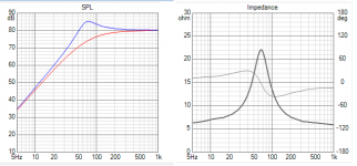
The response of this system, is the impedance of the speaker. This is the trick most often used to measure the impedance of a loudspeaker.
If the impedance of the spaeker is flat (normalizes to 1)., then the output R of theamplifier makes no difference.

Often usd to flatten the impedance of the loudspeaker — this is how Joe deals with the natural resonance in Esinore.
So maybe we are talking about the same thing from different directions?
dave
The response of this system, is the impedance of the speaker. This is the trick most often used to measure the impedance of a loudspeaker.
If the impedance of the spaeker is flat (normalizes to 1)., then the output R of theamplifier makes no difference.
Often usd to flatten the impedance of the loudspeaker — this is how Joe deals with the natural resonance in Esinore.
So maybe we are talking about the same thing from different directions?
dave
- Home
- Amplifiers
- Solid State
- Current drive for Loudspeakers