On average, only around 30% of the length of the VC is in the gap. The inductance we measure across the entrire voice, pretty much is only developed in that gap, only that part of the VC.
Are you sure most of the inductance is in the gap? I'm thinking it goes up when it's unloaded, and goes down when there's a load. Just like with transformers, if there's no secondary load, there's very little AC current on the primary side. And when the speaker has a reduced load because of its bass resonance, the impedance spikes up as well.
Are you sure most of the inductance is in the gap? I'm thinking it goes up when it's unloaded, and goes down when there's a load.
Interesting notion, but nope.
And when the speaker has a reduced load because of its bass resonance, the impedance spikes up as well.
The LF spike is the motional impedance. The steady rise from around 200 Hertz and up in the inductive impedance.
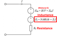
They were shown earlier as:
The three series components are seen in a standard impedance plot:
Motional back-EMF, same as Em, also known as the motional impedance. Not that being a form of back-EMF also means that it is a voltage [EMF] source that shows up as an impedance in the impedance plot.
Inductive back-EMF, same as Ei, also known as the inductive impedance. Again a back-EMF that shows up as an impedance and is also a voltage [EMF] source.
Resistance, same as Rc, the DC resistance of the voice coil and is constant with frequency.
Note that they are all in series and adding up. At LF Em dominates and higher up Ei dominates.
Here is a slight complication as it seems not to show up in the model above. This is the Microphonic back-EMF.
This usually does up in the area (frequency) where the inductive impedance operates. It is usually caused by imperfections in the driver or it can also be caused by the box design where box resonance can show up in the impedance plot.
What happens is that any imperfection in the speaker system can make the inductive impedance unstable.
Then the whole impedance stability is affected because all the elements are in series.
The impedance can be modulated by a number of things, including driver design, box design, ostensibly crossover design can have both positive and negative effects on it (I posit that 1st order crossovers can stabilise the inductive impedance and other crossovers do not, but that is another topic).
So it can be seen why microphonic back-EMF is incorporated inside Ei inductance. This is the main cause of instability. Also excursions can cause the indctance to rise when the cone goes in (+) and go down when the cone goes out (-).
There is a lot more to be said, but what we see is that the stable impedance/resistance of the VC is made unstable by Em and Ei.
The result is that impedance modulations = current modulations when the amplifier is a voltage, but not so much with current drive.
This is why the current source in various measurements, some shown online, indicates lower distortion. The force-factor is related to the current of the amplifier and not its voltage. Mentally sorting this all out is not easy.
As for inductance only really showing up in the gap is logical?
The part of the coil (Xmax) that sticks out at of the gap, will act more like a wire-wound resistor than an inductor. The gap is where the magnetic circuit is focused and also where the force (causing sound) is applied to the VC. So websites like Purifi Audio, the connection is often made between that force and inductance, as being related.
Attachments
Trust me, not an issue. I know what you mean, the idea that with a high source impedance something will show up compared to voltage source. It does not behave differently provided two things are in place: 1) that you have matched the current and 2) that it is the same frequency. And in case somebody asks, there is no stored energy in one that is not in the other.
Why?
The damping comes from the current changing with changing frequency, in a very ordered way.
This is what happens when the amplifier is a voltage source, but it does not happen with a current source. In the latter case, the current that we measured at our original frequency has to change for the damping to be realised. The damping does not show up at one single frequency. I know that many will find this hard to believe, but once you have figured it out, it makes sense.
While Esa Merilainen is an ardent proponent of current drive, and I am not, he would know from the above that the idea of there being a braking mechanism is just not correct and that there is no overhang, just a changed level that corresponds to the current changing. On that score we are in 100% agreement. But out there, that is very hard to get across.
I could go into it a lot deeper...
Allen, there is something that is just a mind-blowing fact that I don't want to mention here, not yet. It's something that turns everything on its head. It is the reason why nobody is doing current driving on the bass.
As you have no doubt noticed, a number of active speakers now available commercially use current drive on the midrange and tweeter (among them Stuart Ralston in Melbourne), but for seemingly good reason, not on the bass.
I have gotten together with Serhan & Swift and we have been talking about the possibility of coming out with a 3-Way active speaker system with all-current-drive on all three drivers. This would include on the bass and the incentive is that nobody has done this before. Each speaker will have a 3-position switch on the back where three different sealed box alignments can be chosen, Butterworth, Bessel and Chebyshev. The three Q's will be around 0.56, 0.71 and 0.85 - just make your selection.
Give me a call and I will tell you how it's done, and what is more, you will understand how it works, the whys of it. But I will also ask that you will keep in confidential. I suggested to Morris Swift, who had in mind taking this to a London Hi-Fi Show, that 'experts' would come into the room and believe it was snake oil. But it isn't, just 100% physics.
I hope I have challenged you. My number is not hard to find, it top of the page www.customanalogue.com, and I will explain it to you.
As I understand it, hifi enthusiatsts need to adjust bass alignments in valve amplifiers to deal with output impedance and the realities of output transformers. I was planning to show you my work on it at the club if I had the time.
How do you see people using switchable damping?
How do you see people using switchable damping?
As I understand it, hifi enthusiatsts need to adjust bass alignments in valve amplifiers to deal with output impedance and the realities of output transformers. I was planning to show you my work on it at the club if I had the time.
Yes, adjusting alignments such as increasing the length of the vent (if vented), or basically make sure the alignment can handle a variety of amps.
I wouldn't mind you showing me, but what I am talking about is somewhat different.
So let me try explain a bit further, start with what we both know:
Increasing the series impedance, whether higher valve/tube output impedance., or series cable resistance or resistance in inductors, all they can do is increase the Qc of the box. I am keeping it simple and hence I am referring to a sealed box. Mainly because this is about something that only works in a sealed box (and with switch).
What is important is that under voltage drive, we can only make the damping worse. We cannot make the output impedance any lower than zero, in fact we can't even make it that in the real world.
So under voltage drive we can only make the Qc go UP.
All agreed. But here come the snake oil bit:
Under current drive we can only make the Qc go both UP and DOWN.
'Hang on Joe, you are pulling the wool over our eyes.'
'Impossible!'
But is it?
Has something obvious been missed or overlooked?
The mechanism/technique I am on about, is not in any textbook.
There are even maths involved. I can think of only one famous speaker designer that also happens to be a full on physicist, and he understood it perfectly when I had him look at it.
I sort of gave you a clue earlier. Note what I said early on about a single LF frequency, that if the current is the same, the the sine wave will be the same - not dependent on the source impedance of the amplifier if the current is the same? I was part leading you to what goes on.
Indeed the high output impedance of the amplifier does not mean that the damping has disappeared. Not when it can be recovered and even increasing the damping. In fact, under these conditions, current drive can become more versatile.
Now I know that I am in a heap of trouble...
Another appetiser: Can a current source drive a dead short and what happens if you do that? What about something close to being a short, but isn't?
I will pause here.
Ok.what I am talking about is somewhat different.
Say that I disagree. Would this demonstrate that? (Naturally, the red driver#1 has been level shifted -2dB)So under voltage drive we can only make the Qc go UP.
All agreed.

I think you have misunderstood what I said, I thought I was specific enough.
If you have a 2nd order Butterworth sealed alignment and around 20 Litres, Qc is the 0.71 and if Fc is 50Hz, then the response at 50Hz will be -3dB.
A Bessel would be closer to -5dB and Chebyshev around -1dB to -2dB at Fc.
If you add any series impedance other than zero, then Qc will go UP. Maybe 0.8 or maybe even higher. It cannot go down.
But with current drive, the same driver and same box, you would get a high Qc of maybe 3. The series impedance makes it like that.
What I am say is that if you know what you are doing, you can virtually dial in the Qc, from 0.5 critically damped, right up to 3.
Variable Qc in the sense that a switch could be used to choose between Bessel, Butterworth or Chebyshev, value 0.56, 0.71 and 0.85 seems to be a good choice. But make it interesting for matching in different rooms. This is something that can only be done if you have current drive and you are not stuck with a Qc of 3.
I am definitely talking about something you have not come across before.
Not so. Here's the series version. You can lower the Q from a Voltage source with no insertion loss...If you add any series impedance other than zero, then Qc will go UP. Maybe 0.8 or maybe even higher. It cannot go down.

It would be, but you'd need to be more abstract to locate it.is not in any textbook.
you can make it negative no problemWe cannot make the output impedance any lower than zero, in fact we can't even make it that in the real world.
dead short no problem, the same as dead open for voltage amp no problemAnother appetiser: Can a current source drive a dead short and what happens if you do that? What about something close to being a short, but isn't?
100 Hertz?
Try 50 Hertz.
But how would you do it with a current source? I ask because knowing that answer makes us understand something about how speakers work.
This thread was about current drive, wasn't it?
Yes, very smart, hahah. I have often referred to negative impedance amps. Do you have any lying around because I don't know who does.
I was of course talking about regular amplifiers which are voltage sources and desirably near zero output impedance. I would have thought that was obvious. You connect cables, inductors, valve/tube amps, all in series, the regular garden stuff we all have to deal with.
Try 50 Hertz.
But how would you do it with a current source? I ask because knowing that answer makes us understand something about how speakers work.
This thread was about current drive, wasn't it?
you can make it negative no problem
Yes, very smart, hahah. I have often referred to negative impedance amps. Do you have any lying around because I don't know who does.
I was of course talking about regular amplifiers which are voltage sources and desirably near zero output impedance. I would have thought that was obvious. You connect cables, inductors, valve/tube amps, all in series, the regular garden stuff we all have to deal with.
AllenB shows shunt network in post #666, if it is tuned the driver/box resonance it lowers Q. Its parallel with high amplifier output impedance, a low impedance path. Circuit impedance seen by the driver is now (mostly) through this low impedance path and not through high amplifier outout impedance, around frequency where the notch is tuned to.But how would you do it with a current source?
The shunt is parallel to driver as well and some amplifier output current flows past driver as well, its a notch filter with high output impedance amplifier.
AllenB shows shunt network in post #666, if it is tuned the driver/box resonance it lowers Q
Works with a voltage source!
Forget it then.
I thought this thread was about current drive. Yes I am familiar with all that clever stuff (I don't need somebody how to create a negative impedance amp, thank you very much), it's all well and good, but I thought it was reasonably obvious what I said and in the context that I said it. I was trying to guide the conversation down a certain way, but that seems not to be possible.
I will ask it again: Can you achieve the same thing with a current source?
Yes!
Say that I disagree. Would this demonstrate that? (Naturally, the red driver#1 has been level shifted -2dB)
I agree that it is a neat trick. But this is still a voltage source, so some would say that the amplifier still has damping because it is a voltage source. I would disagree.
But you did something else not obvious. Think about, and the phrase that I used earlier, that damping is related to current versus frequency. Analyse what your tuned network did on the current side of the amplifier. And the fact you are using a tuned circuit, bravo!
If you could do the same with a current source, then you have proven that damping has nothing to to with the amplifiers output impedance.
This is what I am getting at. The idea that the amplifier provides damping would be disproved if what I am saying is right. Surely the day must come when we say that amplifiers have any real say in the damping as such. Indeed, as your example shows, by manipulating current versus frequency, you have shifted the alignment, and very cleverly at that. But the real damping LF wise is totally defined by the alignment of the speaker and not that of the amplifier.
And it is all explained and clear if you look at what the current does.
Now hopefully we are back on topic, because this is where the heart of the matter lies.
We are going in circles.... meh....
Again:
Again:
- Drive impedance determines electrical damping, from none (current drive aka force-steered mode) to -- theoretically -- infinite (Zout = -Re aka full velocity-controlled feedback with VC as the sensor). That is, also damping to external events like famous knuckle test and to internal error signal like from overdrive recovery. Regardless of dialed-in frequency response (see below) undamped systems will ring with their inherent Q when excited, and may even show chaotic large-signal behavior ("jump resonance").
- Frequency response is, well, just that and any "alignment" follows directly from it. FR can be dialed in arbitrarily via pre-EQ of the signal. Regardless of applied damping. Without any electrical damping the proper counter-EQ at resonance sure is possible but you run into real-world issues because neither frequency nor Q-factor of that resonance peak is stable.
And that's why little progress is being made... until it is. Because you can't stop it even if you think it has already stopped.
This is what some people can only see:

This is what some people can only see:
Yes, of course, trivially so. The driver does not know about the source impedance. When its terminal voltage (or current) is the same the output is the same, obviously. But, as mentioned, the fine print is different (distortion and error recovery).I sort of gave you a clue earlier. Note what I said early on about a single LF frequency, that if the current is the same, the the sine wave will be the same - not dependent on the source impedance of the amplifier if the current is the same? I was part leading you to what goes on.
I DO actually understand speaker physics and the amplifier to speaker interface so your attempted attack goes into the voids. Over and out.And that's why little progress is being made... until it is. Because you can't stop it even if you think it has already stopped.
This is what some people can only see:
View attachment 1141700
The shunt is parallel to driver as well and some amplifier output current flows past driver as well, its a notch filter with high output impedance amplifier.
Teemu, enlarge on that please...
- Home
- Amplifiers
- Solid State
- Current drive for Loudspeakers