When you increase impedance with L-pad or series capacitor around the compression driver main resonance frequency, the electronic damping lessens. The driver diaphragm can now move more at its resonance by external forces, like pressure in the compression chamber.
Perhaps there is enough difference you can hear it, try reduce impedace for driver load to increase electronic damping. If you need to pad use series resistor and parallel inductor. The inductor does highpass, resistor prevents shortcircuit for amplifier and does the pad part. The inductor would provide low impedance path for the electronic damping and higher impedance higher up for distortion reduction.
Perhaps there is enough difference you can hear it, try reduce impedace for driver load to increase electronic damping. If you need to pad use series resistor and parallel inductor. The inductor does highpass, resistor prevents shortcircuit for amplifier and does the pad part. The inductor would provide low impedance path for the electronic damping and higher impedance higher up for distortion reduction.
I didn't compare them, maybe I'll try.Accounting for slightly different fr response, how does the L-pad compare with a series resistor without the parallel resistance?
Yep, it has resonance main resonance frequency (with parallel resistor very low, with capacitor high). But 350 Hz resonance hardly affects the sound of high frequencies. At any volume level, from the quietest.When you increase impedance with L-pad or series capacitor around the compression driver main resonance frequency, the electronic damping lessens. The driver diaphragm can now move more at its resonance by external forces, like pressure in the compression chamber.
I can not even dampen this resonance using only one capacitor, and the sound has an improvement of the quality without a series resistor.
E.g. series 8 ohm and 4ohm parallel, resonance is damped, sound is not so good as without series resistor.Perhaps there is enough difference you can hear it, try reduce impedace for driver load to increase electronic damping. If you need to pad use series resistor and parallel inductor. The inductor does highpass, resistor prevents shortcircuit for amplifier and does the pad part. The inductor would provide low impedance path for the electronic damping and higher impedance higher up for distortion reduction.
Ok, I think that I didn’t explain the difference well enough, better to illustrate with pictures of measurements, maybe I’ll do it on the weekend. Although this may just be offtopic in this thread. I was hoping there was some simple answer 🙂
Do you have any thoughts on the autoformer? How does it work - as a voltage source? Considering that it converts part of the voltage into current, as far as I understand.
Correct, but i am also thinking about audibility and size of this error. I don’t see it can be large. Didn’t investigate it, but i believe dc offset is small compared to actual cone travel. This dc offset can ring at natural resonant frequency which is usualy close to 20hz. If it is small in size it is hard to hear. Audibility of low frequencies is prety bad. Need some displacement/SPL to hear it. My take is from practical side. But if you have measurements on the topic it would be very intersesting to see. I am also interested to know things better 🙂The point is that even seemingly small distortion like 1% (measured steady-state) can be already enough to introduce dynamic DC offset shift of the VC. When the stimulus ends (or changes), the dynamic DC offset changes and it does that move to the new offset position with the natural damping Q.
Exactly!
Current drive only addresses a few of many the error mechanisms in speakers (in particular, Le(x) and Le(i), and power compression) and only when those mechanism dominate then current drive will result in better performance, when restricted to the frequency range where it doesn't have negative side effects, that is.
That the classic view. Played by the book. Textbook. End of story? But is it?
I think it is much more fluid than that. I don't think the book has been closed on the subject. Not yet.
Here's a free idea...
A 1st order low-pass for the mid and/or tweeter, using a small inductor, and equalizing it actively, borrowing inspiration from the RIAA system.
What would the implications be? All positive? Or do we want to avoid over-amplifying?
A 1st order low-pass for the mid and/or tweeter, using a small inductor, and equalizing it actively, borrowing inspiration from the RIAA system.
What would the implications be? All positive? Or do we want to avoid over-amplifying?
Yes, thats what I'm doing. The thing is to reduce distortion current at least at cone breakup, which would amplify any. If series inductor is not suitable then use parallel notch (in series with the driver).
Here is the nugget, why people would argue passive speakers sound better than active? While there is probably many things the main difference between the two types of frequency response manipulation is the driver load impedance.
Well, it doesn't matter what the system is, its always benefitical to know whats happening and how to manipulate for better sound. This current drive thing, impedance manipulation, is just one.
I use a hybrid crossover (passive LRC + EQ) all time, I found if you don't overload drivers and use it creatively to find good crossover behavior, 15-18 dB EQ has no negative impact on sound quality. With CD/horn it's easier to apply, than with tweeters.A 1st order low-pass for the mid and/or tweeter, using a small inductor, and equalizing it actively, borrowing inspiration from the RIAA system.
Well, I would agree that at the moment there still is room for development of transducers optimized for current drive in some way or another.That the classic view. Played by the book. Textbook. End of story? But is it?
I think it is much more fluid than that. I don't think the book has been closed on the subject. Not yet.
But basically the subject of what current drive can solve and what it cannot solve is closed. You sure are aware of the work of the Klippel research company, Mr.Klippel and his team are considered one of the world's leading experts when it comes to scientific analysis and engineering solutions for loudspeaker design and measurement (people skilled in the art, like @lrisbo would certainly agree). Their roots are founded in the former German Democratic Republic which means that these guys are thorough, really thorough, I mean it.
Quoting from https://www.klippel.de/fileadmin/_m...pensation_of_Transducer_Nonlinearities_02.pdf, pages 3ff:
"Instead of driving the loudspeaker with a defined voltage provided by a low impedance source it is also possible to drive the loudspeaker with a current source controlled by the input signal [8]. The current source has a much higher output impedance than the input impedance of the loudspeaker. Thus, variations of the voice coil inductance Le(x) versus displacement x have no effect on the input current i and the mechanical driving force BL(x)i. However, the practical benefit of current drive is questionable. The reluctance force
Frel = 0.5*dLe(x)/dx * i^2
which is a second effect of the nonlinear inductance Le(x), and other mechanical or acoustical nonlinearities can not be compensated by current drive."
The immediately obvious observation that current drive does nothing to solve BL(x), BL(i), Kms(x) etc etc isn't even stated, because it is, well, trivially obvious. At a closer look, it even makes some problems worse, see for example Tymphany AES paper https://www.researchgate.net/profil...f6172/Jump-Resonance-in-Audio-Transducers.pdf
Please checkout the large database Klippel kindly shares, for example:
https://www.klippel.de/know-how/literature/papers.html
https://www.klippel.de/know-how/literature/poster.html
A good starting point is this paper:
https://www.klippel.de/fileadmin/klippel/Files/Know_How/Literature/Papers/Loudspeaker Nonlinearities_Causes,Parameters,Symptoms_06.pdf
Hi, I have no idea what autoformer is, a transformer?🙂 Never saw one here on forums in crossovers so perhaps they are not very useful? I'd avoid any coils with metal core due to additional saturation and hysteresis.Yep, it has resonance main resonance frequency (with parallel resistor very low, with capacitor high). But 350 Hz resonance hardly affects the sound of high frequencies. At any volume level, from the quietest.
I can not even dampen this resonance using only one capacitor, and the sound has an improvement of the quality without a series resistor.
E.g. series 8 ohm and 4ohm parallel, resonance is damped, sound is not so good as without series resistor.
Ok, I think that I didn’t explain the difference well enough, better to illustrate with pictures of measurements, maybe I’ll do it on the weekend. Although this may just be offtopic in this thread. I was hoping there was some simple answer 🙂
Do you have any thoughts on the autoformer? How does it work - as a voltage source? Considering that it converts part of the voltage into current, as far as I understand.
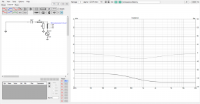
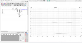
Here is example how you can analyze you situation in VituixCAD, replace amp with short and move the source (amp) next to driver so impedance plot shows impedance series with the driver. Plot the variations you've tried and see impedance for driver load. You probably want "low" impedance for driver resonance to dampen itself and "high" impedance to reduce distortion current.
Here are few of your variations as I've understood:


As you see impedance is reverse what we want. Its "high" on drivers resonance (low frequencies) reducing electrical damping and lowish on pass band allowing any distortion currents. On all these configurations.
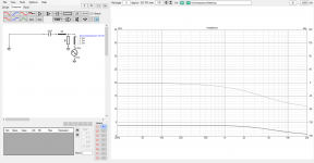
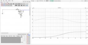
You can reconfigure the system like this instead. Try realistic values for resistor and inductor, I don't know what they are for your application.

As you see impedance as driver load is now completely opposite than with series cap + pad. Its low around drivers resonance allowing perhaps more electronic damping and rises above to reduce any distortion current. The coil in parallel provides low impedance path for damping current. Frequency response can be roughly similar as with cap + pad, see #685
While any / none of these might sound better than the others in you system and application, you just need to iterate them through to find out as KSTR suggested. I would configure your compression drivers side by side and listen them without rest of the system. I mean, setup one driver with your favorite settings as benchmark and then setup the other one with any of the iterations so that you can listen both ABX style. Adjust DSP to match the frequency responses within 0.5db or so. If you hear difference between the setups then you have a better sounding one. Otherwise you could use any of the configurations and call audible difference bias and be happy 🙂
Last edited:
Yes. An auto-transformer is a transformer that uses a single tapped winding, but it works like a regular transformer.what autoformer is, a transformer?
There may be an elephant in the room: cheapness in speaker design.
Why does everyone use low-cost conductive iron cores in their magnets? Even the cheapest transformers use laminated sheets to reduce unwanted eddy currents. Maybe the laminations would do more harm than good, but what about powdered iron cores?
And electromagnets? Wouldn't that enable proper detection of the forces between the 2 coils? Class-A amps often use constant current sources anyway, so a power amplifier could be reconfigured to supply power to both.
Many ways to skin a cat 🙂 Yes stuff like that is doable (probably, I'm no amplifier xpert), its just not as easily interchanged to another. I mean if you have class A amp that also powers magnets in your speakers you can't just swap the amp nor speakers to another one when fashion changes. The amp is paired with the speaker. Nothing wrong with that either, its just not good marketing / money making for industry, if it was we would have lots of systems like this available.
As DIYer you can and should do what you want, what gives most performance/fun you look for, never minding about potential monetary returns of those decisions. Its a money sink no matter what you DIY 🙂
As DIYer you can and should do what you want, what gives most performance/fun you look for, never minding about potential monetary returns of those decisions. Its a money sink no matter what you DIY 🙂
Last edited:
Klippel is correct. Current drive only elliminates the modulation of the blocked impedance (Le) and leves the Force factor Modulation (as we call it and Klippel calls reluctance force whilst other name it flux modulation). However, the pesky hysteresis distortion is in reality that Le changes abruptly with time as the current passes prior reversal points. This distoriton grows with frequency and we can benefit form adding more impedance in series with the driver towards higher frequencies, e-g- by adding an air cored inductor. For the same reason, series damping resistors are better than Lpads for taking a tweeter down in sensitivity.Well, I would agree that at the moment there still is room for development of transducers optimized for current drive in some way or another.
But basically the subject of what current drive can solve and what it cannot solve is closed. You sure are aware of the work of the Klippel research company, Mr.Klippel and his team are considered one of the world's leading experts when it comes to scientific analysis and engineering solutions for loudspeaker design and measurement (people skilled in the art, like @lrisbo would certainly agree). Their roots are founded in the former German Democratic Republic which means that these guys are thorough, really thorough, I mean it.
Quoting from https://www.klippel.de/fileadmin/_m...pensation_of_Transducer_Nonlinearities_02.pdf, pages 3ff:
"Instead of driving the loudspeaker with a defined voltage provided by a low impedance source it is also possible to drive the loudspeaker with a current source controlled by the input signal [8]. The current source has a much higher output impedance than the input impedance of the loudspeaker. Thus, variations of the voice coil inductance Le(x) versus displacement x have no effect on the input current i and the mechanical driving force BL(x)i. However, the practical benefit of current drive is questionable. The reluctance force
Frel = 0.5*dLe(x)/dx * i^2
which is a second effect of the nonlinear inductance Le(x), and other mechanical or acoustical nonlinearities can not be compensated by current drive."
The immediately obvious observation that current drive does nothing to solve BL(x), BL(i), Kms(x) etc etc isn't even stated, because it is, well, trivially obvious. At a closer look, it even makes some problems worse, see for example Tymphany AES paper https://www.researchgate.net/profil...f6172/Jump-Resonance-in-Audio-Transducers.pdf
Please checkout the large database Klippel kindly shares, for example:
https://www.klippel.de/know-how/literature/papers.html
https://www.klippel.de/know-how/literature/poster.html
A good starting point is this paper:
https://www.klippel.de/fileadmin/klippel/Files/Know_How/Literature/Papers/Loudspeaker Nonlinearities_Causes,Parameters,Symptoms_06.pdf
at frequencies below fs, a strong linear motor acts as a motional servo when the coil is voltage driven. The v*Bl back EMF acts as a feedback compensation. and this can actually suppress distoriton form a nonlinear suspension to some degree. This mechanism is lost in current drive
yes - they dont have magnetic hysteresis (no steel close to the coil) and Le(x) is low and constant.
The PURIFI drivers are designed for constant and low Le(x) and sigificant reduciton of the hysteresis distoriton. hence most of the advantages of current drive can be obtained with voltage drive
The PURIFI drivers are designed for constant and low Le(x) and sigificant reduciton of the hysteresis distoriton. hence most of the advantages of current drive can be obtained with voltage drive
Thank you - that was a good answer to my question earlier in this thread, where I was mislead to think there actually was.
voltage drive: Vout= Vin*gainwhaattt!
This is crazy !
Something can not be JUST current driven.
Wherever there is a current there must be a voltage.
Unless you have a loudspeaker with 0 R.
Now , if you took a dual VC sub and fed back the 2nd coil's EMF
back to the amp , you might have something there .... but (I) is never
alone.
OS
current drive Iout = Vin*gain
- Home
- Amplifiers
- Solid State
- Current drive for Loudspeakers