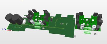
That’s a great little chassis test bed. I have one I’ve put a couple different amp modules in. Currently have @abraxalito class D amp boards in it. Do you plan to have a circuit for the meters? Looking forward to your developments.Toshiba SC-330

Hi Juma sir,
Original jfets are hard to find in our location
is it possible to work the amplifier using BJT instead of jfets
If so, Could you please share the BJT version of this amplifier?
Original jfets are hard to find in our location
is it possible to work the amplifier using BJT instead of jfets
If so, Could you please share the BJT version of this amplifier?
Juma sir,
I have built the cubie3 bjt version and its working fine, but the DC offset is showing around 71mv after 30min of working ,is it normal ?
If not, how to reduce dc offset?
I have built the cubie3 bjt version and its working fine, but the DC offset is showing around 71mv after 30min of working ,is it normal ?
If not, how to reduce dc offset?
DC offset up to 100mV is not a problem but if you want to make it lower, the easiest way to do it is to put a serial connection of 120R resistor+ 50R multiturn pot instead of R8 or R5 so you can adjust it....DC offset is showing around 71mv after 30min of working ,is it normal ?...
Of course, there are other methods: transistors' thermal coupling and/or transistors' matching as well as adding a DC servo circuit etc... There are a lot of posts/threads on these subjects, be free to search the forum/net.

Last edited:
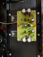
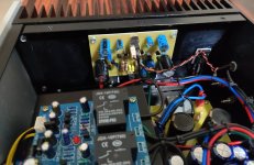
Since there are several solutions, it would be easier to offer the easiest solution if you would include more information of your layout, especially a photo. You will notice from post #1 that juma included a pot in series with a slightly smaller value of R8. If adding in a pot makes it too messy on your layout, then you could find it easy to parallel a resistor with R5 to bring the R8 to R5 leg slightly more negative. That is if the present offset is +71mV and not -71mV. Maybe try a resistor value between 2k2 and 3k3. Small steps are better than big jumps. After you see the amount of change you can use the formula for parallel resistance to calculate a better value resistor.
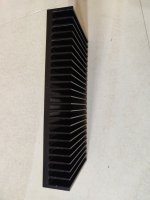
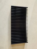
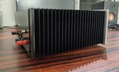
Would you also measure and post the amount of heat rise you have along with a photo of your heat sink? That may help others judge how much heat sink they need for this circuit. It looks like a very nice circuit that needs only low-cost, easy to obtain parts.
Would you also measure and post the amount of heat rise you have along with a photo of your heat sink? That may help others judge how much heat sink they need for this circuit. It looks like a very nice circuit that needs only low-cost, easy to obtain parts.
Thanks sirDC offset up to 100mV is not a problem but if you want to make it lower, the easiest way to do it is to put a serial connection of 120R resistor+ 50R multiturn pot instead of R8 or R5 so you can adjust it.
Of course, there are other methods: transistors' thermal coupling and/or transistors' matching as well as adding a DC servo circuit etc... There are a lot of posts/threads on these subjects, be free to search the forum/net.
Currently, I don’t have anything to measure the temperature. After 3 hours of working, temperature of lateral mosfet is normal only.Since there are several solutions, it would be easier to offer the easiest solution if you would include more information of your layout, especially a photo. You will notice from post #1 that juma included a pot in series with a slightly smaller value of R8. If adding in a pot makes it too messy on your layout, then you could find it easy to parallel a resistor with R5 to bring the R8 to R5 leg slightly more negative. That is if the present offset is +71mV and not -71mV. Maybe try a resistor value between 2k2 and 3k3. Small steps are better than big jumps. After you see the amount of change you can use the formula for parallel resistance to calculate a better value resistor.
Would you also measure and post the amount of heat rise you have along with a photo of your heat sink? That may help others judge how much heat sink they need for this circuit. It looks like a very nice circuit that needs only low-cost, easy to obtain parts.
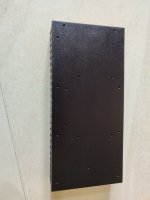
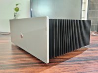
I think below mentioned heatsink size is appropriate
Length-25cm Width-4cm Height-11.5cm
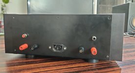
Please find the attached snap for reference
Attachments
Sir, can i use 100ohm multiturn port?DC offset up to 100mV is not a problem but if you want to make it lower, the easiest way to do it is to put a serial connection of 120R resistor+ 50R multiturn pot instead of R8 or R5 so you can adjust it.
Of course, there are other methods: transistors' thermal coupling and/or transistors' matching as well as adding a DC servo circuit etc... There are a lot of posts/threads on these subjects, be free to search the forum/net.
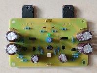
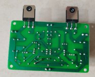
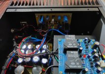
Completed the cubie3 JFET version with k246 & j103 JFETs
Sound is amazing 😱
Sound is amazing 😱
Attachments
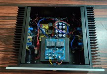
These days I finished my Cubie.
It uses 7ma jfets, j77 and k216 in the vas, 08n16v and 08p16v outputs.

I run the vas at 30ma.

When I increase the bias above 100ma the amp starts to oscillate.
If the input is not connected the oscillation is smaller

If I ac couple the input to a signal source I get this

Power comes from a 28vac dual secondary trafo
What could be the cause of this?
It uses 7ma jfets, j77 and k216 in the vas, 08n16v and 08p16v outputs.
I run the vas at 30ma.
When I increase the bias above 100ma the amp starts to oscillate.
If the input is not connected the oscillation is smaller
If I ac couple the input to a signal source I get this
Power comes from a 28vac dual secondary trafo
What could be the cause of this?
Seems I spoken too soon.
Yesterday I removed the gate resistors from the vas and set the bias fixed at 130ma for the each channel by replacing the pot with a fixed resistor.
Ran a couple of square waves and everything looked fine.
The front end runs at 5.5ma, the vas at 20ma and no sign of oscillation.
Today I placed back the pots to be able to set a higher bias and the oscillation appeared back.
When I increase the bias in the ops the mosfets in the vas go south and draw 50ma.
Any ideas what can I search for?
- Home
- Amplifiers
- Pass Labs
- Cubie3