

I get it. I was seeing the arrangemt on the schematic as being somehow more complex than that, but now I see they are simply paralleled. Cool, got it. Thanks!!!
Hi Juma ,
Cubie 3 could work with BC550 - BC560 in place of 2sk170 - 2sj74 , what would you change ?
best regards
Cubie 3 could work with BC550 - BC560 in place of 2sk170 - 2sj74 , what would you change ?
best regards
Few parts and connections between them 😀
Basically it comes down to biasing/polarisation differences between BJT and JFET and there are quite a few ways to do it...
Basically it comes down to biasing/polarisation differences between BJT and JFET and there are quite a few ways to do it...
I am going to etch a pair of CB3 PCB's. What are the electrolytic capacitors voltage ratings? My JFETS have an Idss of 3.2 mA, do I need to change anything?
Also, does anyone have the Mouser part #'s for the BC547C , BC557C semi's?
Thank you both Juma and Marsupialx. 😀
Also, does anyone have the Mouser part #'s for the BC547C , BC557C semi's?
Thank you both Juma and Marsupialx. 😀
Last edited:
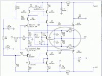
C3=10V, C5=C7=25V, all the rest = 50VWhat are the electrolytic capacitors voltage ratings?
You'll have to lower the value of R4,R6 to 22R - 27R in order to get about 4-5mA through Q5,Q8My JFETS have an Idss of 3.2 mA, do I need to change anything?
You can use the BC550C, BC560C insteadAlso, does anyone have the Mouser part #'s for the BC547C , BC557C semi's?
Hi Juma
I would like to build this circuit for power supply voltages of +-24v.
Right now I use an ACA with a linear ps of 24v which could be rearranged for +-24v. I need a little more headroom with my speakers and this amp would fit fine since my heatsinks are to small for a large class A amp.
Is there anything to change in the circuit? Or should I just watch the current through Q4,Q5,Q7,Q8 and adjust R6 and R4 accordingly?
Thanks in advance
Tobias
Hi Tobias,
for +/-24V PSU just change R16 and R18 to 10k. Q5/Q8 can be changed to BC547c/557c or BC550c/560c
for +/-24V PSU just change R16 and R18 to 10k. Q5/Q8 can be changed to BC547c/557c or BC550c/560c
Hi Juma,
I'm willing to build a Cubie3, as I already have the main parts for the build.
Main problem is: my transformer is a 2 x 36V (300VA), thus I can expect the supply voltage around +/-45V.
My jfets Idss are 6,5 mA, the heatsink are more than adequate (I'm currently using similar ones for an F4) for a "bold" idle current (I'll do some trials).
What I have to (possibly) change?
I suppose, increase R4/R6 to 100 R (?) in order to maintain 4-5mA through Q5-Q8, then change R18/R16 to 24k.
May BC139/140 be used instead of BC639/640 (Q5/Q6)?
Thank you (for the early Xmas gift..)
Guido
Hi Guido,
with 2 x 36V AC you can expect about +/-50V DC ie. +/-45V after the cap multiplier. That's quite a difference compared to original +/-36V. Two pairs of output laterals will be needed, probably a follower stage before them, and few other things should be changed too.
I can't be sure how it will sound with those changes and will it be worth the effort without building the prototype, so if I were you, i would:
1. lose some windings from that transformer to make it 2 x 30V AC, or
2. pick another amp project to build
That's bad news, unfortunately I can't unwind the transformer.
It's time to visit my transformer's supplier...
Many thanks anyway
Guido
It's time to visit my transformer's supplier...
Many thanks anyway
Guido
I just finished this circuit, biased to 350mA and listen to music right now. I am impressed, it replaces an ACA Amp, which is quite nice on my speakers, but compared to this amp it sounds a little bit less open and smaller, with a less dynamic feel.Hi Tobias,
for +/-24V PSU just change R16 and R18 to 10k. Q5/Q8 can be changed to BC547c/557c or BC550c/560c
Great little amp you designed!
Thanks again
Tobias

- Home
- Amplifiers
- Pass Labs
- Cubie3