No you didn't and I really don't care why. I have more important things to do.😉
If you have better things to do, then don`t comment on what you thought that I thought 😉
I agree with that - without fun it's nothing.Cool down, you could ignore the post... This should be fun 😉
It's just that lately I've been targeted by a bunch of a Jon Snows/wanna-bee-scientists...

Thanks for the tip mlackey, I had already scaled the board size, found out it was a MS Paint issue - now fixed.
Hi Juma;
Thanks for this. I have a couple of questions.
Are Q1 and Q2 thermally coupled a la the F-5?
Also; do you think that the BC639/640 could drive two pairs of MOSFETs? I think they probably could but not much more given their bias current. I have an notion to build a 4 channel amp for bi-amping and the bass channel would use parallel output devices.
Thanks
Matt
Hi Matt,
thermal coupling is always beneficial but I didn't implement it here because even without it the DC offset doesn't drift much (few mV up or down).
I didn't test multiple pairs in the output stage but you can:
1) use stronger pair instead of BC639/640 and increase the current through them to 10mA or so.
2) put another BJT pair as EF between Q5,Q8 and the output stage.
Thanks Juma;
I just did some math (should have done that first)...I had to think about it a bit and I think this is right.
Q=CV=it
CdV=tdi. di is the change in current (delivered by the second stage); dV is the change in voltage on the gate of a MOSFET.
If I assume dV is 30V and C is 1.2nf (2 X Cin for a 2SK1058) and t is a quarter cycle at 20kHz (12.5us) the current needed to charge/discharge the gate capacitance is
di = CdV/t
so the change in current is 2.9mA. If the bias current in the second stage is even close to 10mA there should be plenty of margin. I'll probably pick option 1.
Thanks again.
Matt
This project started few months ago when I found a nice R-core transformer in a pile of electro junk at the local flea-market (60V CT secondary, 200VA).
What transformer power is needed for a single channel amp?
The 200 VA spec of you transformer seems to be a "random" value since it's not based on the needs of the amp (you just used what you found).
And how much heat sinking do I need (how much heat/power dissipation per channel)?
...it's not based on the needs of the amp (you just used what you found)...
Not true. Read again post post #1, 2nd sentence. I designed this class AB amp amp to suit the transformer's power and voltage rating.
Heatsinking I used (read post #6) is in accordance with circuit's power rating and intended use.
So I'd look for a 200 VA transformer for a stereo amp, and two 100 VA transformers for two monoblocks, correct?Not true. Read again post post #1, 2nd sentence. I designed this class AB amp amp to suit the transformer's power and voltage rating.
You wrote in post #6 "just about right for 20W constant dissipation". Is this the dissipation per channel, or the total of both channels? And what would be your recommended maximum sink temperature? What I am trying to ask: what kind of thermal resistance spec do I need (for a single mono channel amp)?Heatsinking I used (read post #6) is in accordance with circuit's power rating and intended use.
I have recommended a minimum of 160VA for a power amp transformer.
This is because the regulation of smaller transformers is quite high and this leads to a very high quiescent voltage on the supply rails, that sags badly when higher power is demanded.
This is because the regulation of smaller transformers is quite high and this leads to a very high quiescent voltage on the supply rails, that sags badly when higher power is demanded.
YesSo I'd look for a 200 VA transformer for a stereo amp, and two 100 VA transformers for two monoblocks, correct?
YesYou wrote in post #6 "just about right for 20W constant dissipation". Is this the dissipation per channel
40 deg. Cels. You can go up to 60 but I don't like that - as any decent engineer I despise entropy (anything too hot) 😀 Besides, it influences the long term reliability of PSU capacitors...And what would be your recommended maximum sink temperature?
I don't trust manufacturers specifications - I choose them based on my experience.what kind of thermal resistance spec do I need (for a single mono channel amp)?
Look at these two heatsinks - they are both rated at 0.5 K/W and yet they are very different:
173AB2500B | Heatsink 0.5K/W 250x119x63mm | ABL Components
350AB1500B ABL Components | Heatsink 0.5K/W 150x125x50mm | 271-870 | Welcome to RS Online
None of the both will deliver 0.5 K/W without a helping fan. This one will, although its rating is worse (0.55 K/W):
159AB2000B ABL Components | Heatsink 0.55K/W 200x160x40mm | 234-2463 | Welcome to RS Online
Last edited:
All three of these RS heatsink are made by ABL.
I would expect that all will be rated using the same method that ABL have developed.
I can't see why the higher rated one should actually perform better than the others rated at slightly lower resistance.
All look quite substantial with thick backplates.
Fin depth varies from ~32mm to ~55mm, quite good as far a high dissipation sinks go.
Last edited:
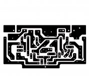
Un-reversed.
Cool, thanks!
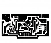
Could you include parts (position, size)?
Which is copper side view (I am confused)? Adding some text label(s) on the copper would help.
Also, could you indicate the dimensions or add markers to make sure things are scaled correctly?
Cool, thanks!
Could you include parts (position, size)?
Which is copper side view (I am confused)? Adding some text label(s) on the copper would help.
Also, could you indicate the dimensions or add markers to make sure things are scaled correctly?
The file here is a low res file. The thing to do is have me email you a pdf of the larger file. PM me your email address. I have not done a part placement, but I will.
I wasn't going to do a Cubie 3, being way more than happy with my Cubie 2, but another very nice DIY member asked me to do it, so I did. I am not, however, mentally equipped for tech support. Others will have to provide that.
The reversed file is for laser toner transfer etching. You are looking at the foil side. I will post a parts placement in the near future.
Last edited:

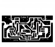
If somebody wanted to go through juma's original post and insert values for all of the parts, (from schemo to juma's layout, that would be very helpful. I'm trying to make sure I don't screw up. It would be a drag if little puffs of magic blue smoke dotted the landscape around the earth because of my mistake.) it's ok if I let the smoke out of my parts, but I'm not building this for the foreseeable future. Thanks. Nobody should etch yet.
- Home
- Amplifiers
- Pass Labs
- Cubie3