1k 25turn variable resistor for Rbias will run at quite high current.
A 500mW 1k has a maximum current of ~22mA.
Some will recommend that a trimmer should be run long term at no more than 50% of max power and others will suggest that long term they be run at no more than 50% of max current.
10mA is already @ ~45% of max current. Be careful that your second stage current is within the current rating of the VR.
Here is your modified artwork no need for bending.
Not tested ..... Yet😀
Greetings
Thanks for the effort. The bend was designed and intentional. Nothing got "torched". It is configured for a very tight mounting space, where the 12 leads from the LatFets are suspension with smooth "give" for expansion / contraction. Just a joke between juma and myself, two humans with different ideas on the proper treatment of leads. You don't have to bend 'em up funny to use juma's layout. Thanks, again.

1k 25turn variable resistor for Rbias will run at quite high current.
A 500mW 1k has a maximum current of ~22mA.
Some will recommend that a trimmer should be run long term at no more than 50% of max power and others will suggest that long term they be run at no more than 50% of max current.
10mA is already @ ~45% of max current. Be careful that your second stage current is within the current rating of the VR.
Thanks, Andrew, I'll get 'em set and replace the little buggers with some nice brown vishay/dales. Plan on doing the same with the 20 ohm, will probably need a stack of three in parallel to get it honed. (Main value close but over, 2nd value calculated to get it closer but still over, and the third value to squeak it exact, or that's the plan.) Or I could get lucky and have it need a common value, (unlikely). Something like 20 ohm, 2k, 200k, or something. I've got handy, dandy online resistor calculators that will do the dirty work.
Last edited:
Thanks for the effort. The bend was designed and intentional. Nothing got "torched". It is configured for a very tight mounting space, where the 12 leads from the LatFets are suspension with smooth "give" for expansion / contraction. Just a joke between juma and myself, two humans with different ideas on the proper treatment of leads. You don't have to bend 'em up funny to use juma's layout. Thanks, again.
marsupialx It was a joke also.🙂 You can see from the smiles I posted to
Anyway I just made the black and white based on your artwork
That PC board is a small cute design, I increased the size so all the 1/2W resister can feet , no need to stand it up al do that is not a problem at all.
I will build these amp to, that is main reason I mode the layout to feet my amp case.
I built several yeas a go a ProFet amplifier and I want to replace that with a newer design.
To be honest the sound of that already boring 😀
If someone want to use these layout ( I did not ask JUMA permission yet, I hope to post here is not a problem) you have to set up your printer to 136 to 138%.
Greetings
Attachments

Yup, no permissions needed. I just prettied up juma's layout, didn't move much. Have fun and report back! I hope Cubie 2 actually out performs Cubie. I have my doubts. Cubie is awesome (within its power limitations). Now I have a serious hankering to build a pair of "take no prisoners" mini-monitors for listening in the near field. Need to sell something to free up some cash.marsupialx It was a joke also.🙂 You can see from the smiles I posted to
Anyway I just made the black and white based on your artwork
That PC board is a small cute design, I increased the size so all the 1/2W resister can feet , no need to stand it up al do that is not a problem at all.
I will build these amp to, that is main reason I mode the layout to feet my amp case.
I built several yeas a go a ProFet amplifier and I want to replace that with a newer design.
To be honest the sound onof that already boring :
If someone want to use these layout ( I did not ask JUMA permission yet, I hope to post here is not a problem) you have to set up your printer to 136 to 138%.
Greetings
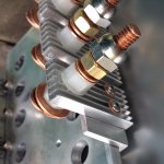
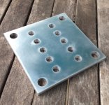
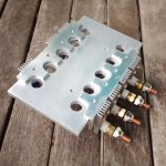
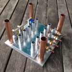
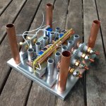
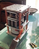
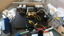
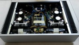
More pics. Cubie 2. Figured on this module I'd take some pics before I actually assemble it.
Attachments
Last edited:
All that tubing and copper makes me think its some sort of waterblock manifold. So pretty you could take it to an art fair and sell them at a nice markup because they are functional art.


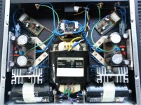
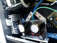
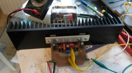
My more ordinary small version 😀 Currently set at 400mA and +/-20Vdc, so it is running quite warm. Problem is the slightly too high voltage of the transformer, so I also had to use a zener in my cap multiplier to clamp off some volts (and those little grey heatsinks are running now at almost 60°C :-/ but the IRFP044 seems not to have any problem with it..) The big case sinks on the side are running at +/- 43°C hottest part, also warm, but I believe it is OK (not using the amplifier when it is > 21°C ambient)
Build with the components I had for other projects that never saw daylight... It really rocks with my 94dB Cabasse speakers! 🙂
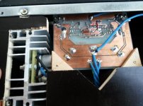
Thinking of implementing a switch that can lower the bias... (for critical live concert listening or soft background ;-) ) but afraid that the offset might change too much when bias changes. Would also like to redo the power supply as I'm not very happy with the layout (although I have no hum whatsoever in my speakers) or I will have to at least change these big elco's on the front side that are not in very good shape as one is quickly loosing its charge without load.
Juma, thanks a lot for such an incredible design, if you have a cold alternative in the same league, please share! 🙂
All the best,
Berny
Build with the components I had for other projects that never saw daylight... It really rocks with my 94dB Cabasse speakers! 🙂
Thinking of implementing a switch that can lower the bias... (for critical live concert listening or soft background ;-) ) but afraid that the offset might change too much when bias changes. Would also like to redo the power supply as I'm not very happy with the layout (although I have no hum whatsoever in my speakers) or I will have to at least change these big elco's on the front side that are not in very good shape as one is quickly loosing its charge without load.
Juma, thanks a lot for such an incredible design, if you have a cold alternative in the same league, please share! 🙂
All the best,
Berny
Attachments
Last edited:
Hi Berny, glad you like it. 🙂
To relax the thermal conditions, it's best to lose some windings from transformers secondaries i.e. lower their voltage.
43°C is OK, you can go up to 50°C with no worries about LATFETs. 60°C is not a problem for IRFP044 but it is for surrounding capacitors - I suppose that's what you meant by "not very happy with the layout".
How much the offset changes with bias change I cannot tell you exactly (it's a small change for sure), but it's easy to find out (just don't forget to disconnect the speakers before the experiment).
When it comes to "cold alternative in the same league" I'm afraid it can't be done with less than 200mA in the output stage no matter how good the measured data looks in various designs that try to achieve that with 100dB of feedback, HEC or similar schemes, bizarre output stages...
Last edited:
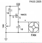
A fluid bearing fan with a simple Nelson Pass speed control is really quiet. Moving some air is good. I built a couple of these right on the potentiometers. The trick of this speed controller is the caps/mosfet provide a little kick to start the fan at a slower speed than
would ordinarily work .-mars
would ordinarily work .-mars
Attachments
Last edited:
It really rocks with my 94dB Cabasse speakers! 🙂
Nice built Berny 🙂
They definitely also rocked my speakers 😉
Nice built Berny 🙂
They definitely also rocked my speakers 😉
..and you found your new challenge/project 😀
Nice built Berny 🙂
They definitely also rocked my speakers 😉
Hi
I read at F5T you will have the access to compare the two amplifier.
If you did please let us know (or me in private) YOUR opinion on both.
How Qubie2 sounded compare your F5T.
Please state your own opinion, I understand and accept that.
The reason I ask you because I'm half in way to have both of these amps.
Thank you very much.
Greetings 🙂
We haven't compared them yet during our chaotic listening session ;-)
It's planned for the next time.
We compared it to a class A/B amplifier and the Cubie2 sounded much better to us.
Cubie2 is a very good amplifier, one to keep.
I don't have a F5T just a F5 (CLC PS, Failchild mosfets)
Regards,
Danny
It's planned for the next time.
We compared it to a class A/B amplifier and the Cubie2 sounded much better to us.
Cubie2 is a very good amplifier, one to keep.
I don't have a F5T just a F5 (CLC PS, Failchild mosfets)
Oh no ! Not another project ! 😉..and you found your new challenge/project 😀
Regards,
Danny
Last edited:
Hi Gaborbela,
We just did another listening session, this time also to compare the Cubie2 with the F5.
In short: choose the Cubie2 to build 🙂
First we listened with some test tracks to the Cubie2, everything sounded very good: holographic, detailed, very good bass, everything sounded correct, it started us foot tapping 🙂
After the Cubie2 the same test tracks with the F5 and immediately we heard that the bass/lower end was lacking/slow, it sounded like there was something missing, it was less involving.
So now I have to make a Juma amp 🙂
The Cubie2 went home with Berny 🙁
@Juma:
Congratulations with such a great design !
Now I'm thinking of building your F5 with 2SK2013/2SJ313 (I have the mosfets) or the Cubie2.
Any advice ?
Regards,
Danny
- Home
- Amplifiers
- Pass Labs
- Cubie2