You can see from the post #1 that I measured my MOSFETs before soldering them in i.e.the test was made to see how much Vgs is needed for Id of 0.7A at Vds of 16V. It was 1.7V for k1058 and 1.6V for j162 for a total of 3.3v over Rbias which dictated it's value of 330 Ohms (having in mind that the current through Rbias is 10mA).Juma, where do I measure to set bias on the Cubie and Cubie 2? What voltage am I looking for to get a medium bias on the 1058 and 1062 latfets? Thanks, sorry I'm not more knowledgable in these things -marsupialx
Since lateral MOSFETs are of pretty similar characteristics I suggest you mount them on the heatsink and put the amper-meter in the +rail and see what reading you get with Rbias=330R. If it's much more than 0.7A lower the Rbias to 270R or, if the current through the output stage is too low bring the value of Rbias up - to 390R or more. Of course, the trimm-pot can be used but the precise value of Id is not very important here, from 0.5 to 0.8 A is OK.
I choose 0.7A as an optimal value for the amp's PSU rails of +/-16V and speakers from 4 - 8 Ohms. If you have enough heatsinking and you wish to experiment you can go for 1A or so...
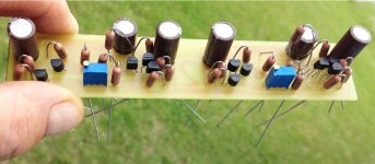

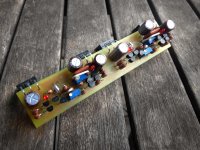
Looks OK if you have tested JFETs and MOSFETs before soldering all the parts because it won't be easy to measure critical values across those stand-up resistors (voltage drop on R10-R13 and Rbias).Cubie is getting stuffed. ...
Dont forget that you have three independent GND points on your PCB (signal GND on each channel and common power GND for output stages decoupling caps) that should meet at main GND of the amp.
Take care about LED's polarity - if all is OK they should be glowing, but not very brightly (there's only about 1mA through them).
Last edited:
20 ohm trimmers on Ebay - 3 x 20 Ohm Trimpot Trimmer Potentiometer 3296W 3296 | eBay
I have a trace connecting the ground from the electrolytics to each other, so I just need to connect that to signal ground on each channel. Should there be any sort of anti-parallel diode/ big resistor isolation, or just a wire?
I'll make sure I leave some lead exposed on the bottom of the resistors for measuring.
Good to know about the led's not being bright.The flat indicated on led in your drawing is negative, (the short lead), correct? Thanks!!!
p.s. I currently have 1K trimmers in the RBias resistor spot. I'm going to be measuring elsewhere, (not across Rbias itself), correct? If I need to measure across Rbias, I need to accommodate with some test points. I can also measure current draw for .7 amps, like I did on Cubie, correct?
Last edited:
That's all it takes.... just a wire?
Anode is connected to higher potential, the flat (cathode) goes to lower potential - check that with DMM (diode setting). Meaning higher or lower than zero, positive or negative is less usefull here - both cathode and anode of D2 are positive, it's just that anode is "more positive"....The flat indicated on led in your drawing is negative, (the short lead), correct?
Across Rbias you'll measure the total Vgs of the MOSFETs and the bias current of the MOSFETs you already know how to measure. Start with the lower value of Rbias - 200R or so.... I currently have 1K trimmers in the RBias resistor spot. I'm going to be measuring elsewhere, (not across Rbias itself), correct?
... like I did on Cubie, correct?

One more thing - you bought trimmers on ebay, and since they need to be of good quality (critical part), check them thoroughly before soldering them in.
Last edited:
After I get the amp dialed in, can I remove the trimmers and replace with fixed resistance, or will it need adjustment (tweaking) periodically? Since you specified fixed resistance for Rbias, I assume no difficulty there, but what about the 20 ohm trimmer? I guess the question could read, how much do you anticipate dc offset to drift over time, and how important do you consider having a pot to tweak it occasionally?
Last edited:
It will drift a couple of tens of mV up or down from cold to hot, depending on thermal setup of the amp's case. Aging won't change it much.
So, final adjusting should be made when the amp is in the case, after hour or two of warming up, with inputs shorted to GND and the case lead on. I doubt that you'll set it tight with fixed resistors, but OTOH even few tens of mV doesn't mean much in real life...
So, final adjusting should be made when the amp is in the case, after hour or two of warming up, with inputs shorted to GND and the case lead on. I doubt that you'll set it tight with fixed resistors, but OTOH even few tens of mV doesn't mean much in real life...
Those are good.Here is the 20 ohm from DigiKey.
3296W-1-200LF Bourns Inc. | 3296W-200LF-ND | DigiKey
Thanks for the suggestions on setting the trimmers Juma and to marsupialx for the link.
I typically order from Mouser and see that they have the same trimmer in stock.
I typically order from Mouser and see that they have the same trimmer in stock.
Marsupialx, I assume the 1K ohm trimmers are for setting the bias?
I wonder if 500 ohm trimmers will also work since Juma initially used a 330 ohm resistor for biasing?
Thanks...
I wonder if 500 ohm trimmers will also work since Juma initially used a 330 ohm resistor for biasing?
Thanks...
That's a question for juma, I have some 500's, I plan on finding the correct value and replacing them with fixed resistors, for that, I think the 1K will suffice.
Aaaaah, it hurts, it hurts......hideous latfet lead bends.😀 ...

500 R trimmers will do do job perfectly...I wonder if 500 ohm trimmers will also work since Juma initially used a 330 ohm resistor for biasing?...
There's no need for bending in the original layout (MOSFETs were meant to be soldered from the bottom side of the PCB - see post #1) - it's just the way our Kansas cubist likes it... 😀
- Home
- Amplifiers
- Pass Labs
- Cubie2