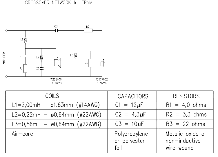
Fine, but notice that the TRYM xover already contains a notch (L2 + C2).Just to be clear I have selected the T25 tweeter and I am building the trims xover and may include a notch.
Ralf
Are you ordering a mic now and doing your own in box measurements?
If not - I am happy to give this a go:
1. Can you please tell me how far back the tweeter is mounted relative to the woofer? Is this via slanted or stepped baffle?
2. Can you please give me overall baffle dimensions - then measure the tweeter and woofer centre relative to the top edge and one side (assuming no driver horizontal offsets)
I can then sim a crossover for you.
Be particular on the notch filter component values - especially if you are only going 2nd order (and not 3rd or more).... and more importantly tolerance. Being 10% out and you can "miss" the required notch frequency. Components with +/-5% or less are preferable.
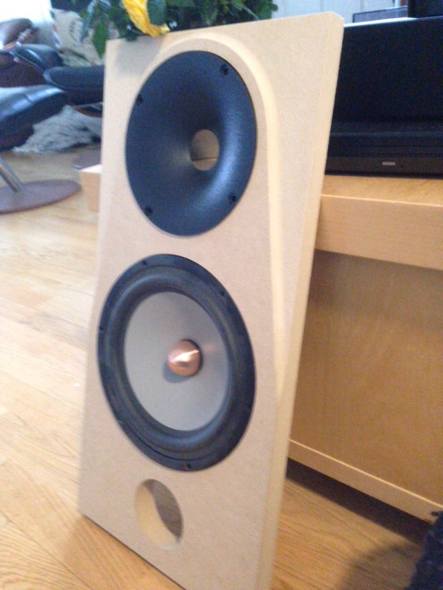
Dave I am going with the Seas T25CF002 with the W22EX001.
Overall baffle dimensions are 305 x 940. The top tweeter baffle is 6mm thick by 160 x 305.
The woofer baffle is 24mm thick with a 45 degree chamfer on both sides and a 22 degree chamfer on the top. Dimensions of front face are 269 x 773. Back face is 305 x 780. So there is a baffle sloped step of 18mm between tweeter and woofer. The cabinet front wall is 18mm giving a total wall thickness at tweeter of 24mm and at the woofer of 42mm.
Tweeter centre is 95 from top. Woofer centre is 287.5mm from top.
I will be interested to see how your simulation and xover differs from the Sub-Chebychev based xover of the TRYM.
Thank you Dave.
In this case the original TRYM xover won't work as it is designed for a flat baffle. 18mm is a lot in term of phase at the xover frequency.So there is a baffle sloped step of 18mm between tweeter and woofer.
Also your baffle width is not what it should be, but that is a secondary problem, you should at least build a flat baffle or add a 18mm sub-baffle for the tweeter.
Ralf
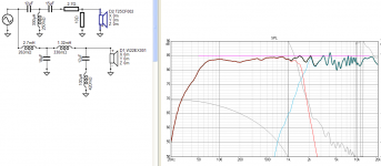
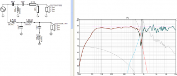
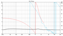
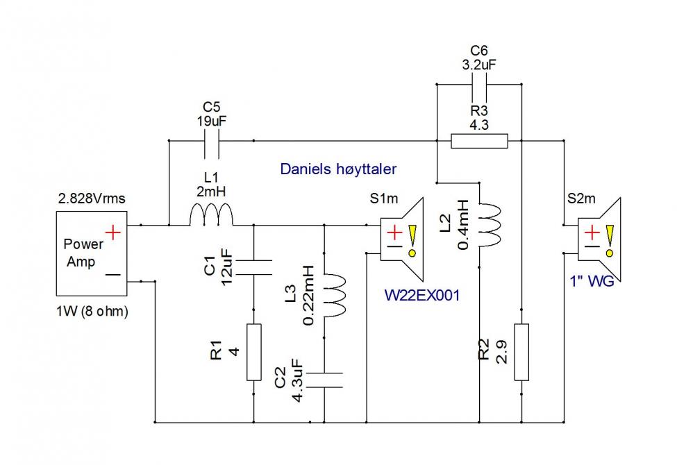
Here's my attempt.
I've assumed a stepped baffle of 18mm - still requiring another 30mm (guestimated) for Z offset to VC centre of the W22 and angle up to the tweeter listening axis. My L26 is ~ 37mm back from the baffle plus the angle up to the tweeter listening axis. I can change this if you can please measure the baffle face to VC centre of the W22 and repost.
I've targeted a LR acoustic steep slopes. I did this for 2 reasons:
1. Avoid W22 breakup
2. Avoid stressing the tweeter
I arrived at a Fc ~ 1639Hz - which really is a little lower for the T25CF002 than I would prefer. the T25CF002 has generous xmax (0.5mm) and with the steep slope applied, I am hoping the woofer shows stress before tweeter issues - but I have not modeled excursion (yet) to find which gives up first.
the simulated in box response of the tweeter used a 0.6m x 0.8m source BDS for the Seas factory measurement (I have assumed a centred "worst case" position on this baffle as it is not stipulated - rather than IEC offset). This results in a lot more ripple.
Secondly, the target baffle I found a peak at 4Khz which may not be there in reality... So I would look at an average response in this reason rather than stressing.
This is where in box measurements will be vital. I am confident when I have good source data - but I'm layering guesses.... Note the reverse polarity of the tweeter.
Feel free to ask questions.
Attachments

Thank you Dave. I appreciate the time this must have taken. I also appreciate the difficulties of using a stepped baffle. I have added to the complexity not only in xover design but also cabinet construction. I am going to take some time now and after the seasons festivities are over hopefully I can make a decision about which direction to follow. I have a great deal to think about.
I wish you all the best for the festive season.
Kind Regards
Martin
I wish you all the best for the festive season.
Kind Regards
Martin
You're welcome Martin. I find these exercises fun and it gives people food for thought. Heck - criticism is welcome.... I learn 🙂
With metal drivers (I use them), the compromise is limited passband or requirement to use more crossover parts to hammer the response into the required shape and / or attenuate the usually severe breakup.
Using drivers that aren't intended to "meet" therefore means even more extreme measures than usual. Hence the extra crossover parts than would otherwise be seen in a conventional 2-way.
Looking forward to your progress in the new year.
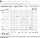
I was messing around with the SEAS TRYM, myself this afternoon. Software | Visaton
I didn't find any solutions better than SEAS came up with:
I find no convincing arguments for stepped baffle here. But maybe waveguides might be a game-changer. Dunno.
I didn't find any solutions better than SEAS came up with:
I find no convincing arguments for stepped baffle here. But maybe waveguides might be a game-changer. Dunno.
A waveguide would certainly be recommended. This should effectively allow a nominally 2000Hz electrical co to achieve the required 1639hz as per my design and reduce tweeter stress therefore distortion. The waveguide however will not address the potentially harsh H3 at 1400hz of the W22. Only the listener could confirm whether tolerable
Have a jolly (careful) Christmas in the bonny toon o' Troon. 
My father was an engineer fitter working on aircraft during WW2.
He claimed he had to fly along with the pilot after repairing an aircraft engine as an assurance of the quality of his work.
He must have meant aircraft larger than a Spitfire, but then again my father was not averse to telling a few tall tails!
Perfectly plausible he’d have to do a ride along. I’ve just spent 20 years working on A320 wings and never had to do one!!
Bit of waveguide stuff from SEAS fanatic wilbur-x:
Seas TRIM (W22EX001 + WG)
Zaph|Audio
Seems to be using a SEAS 27TDFC tweeter, with unchanged SEAS Trym bass filter.
Seas TRIM (W22EX001 + WG)
Zaph|Audio
Seems to be using a SEAS 27TDFC tweeter, with unchanged SEAS Trym bass filter.
- Home
- Loudspeakers
- Multi-Way
- Crossover frequency and filter order advice sought