I'm putting together a pair of three way speakers using some inexpensive Dayton RS series drivers. I'm a newbie at passive crossover design but I've spent some time with couple different versions of software and have come up with a design I think may work in XSim. I haven't taken actual measurements of my drivers yet (haven't had a chance to break them in yet) so I'm using the .frd and .zma files available from Parts Express as a learning exercise and plan to tweak this design once I have the speakers assembled. Also no baffle step correction or driver alignment yet either.
The woofer and mid are both 8 ohm drivers and the tweeter is 4 ohm. I've been trying to keep both the efficiency and the impedance of the speaker up, but I've been struggling with the impedance. I was hoping to end up with 8 ohm speakers but these seem to be looking more like 4 ohm.
Any hints or suggestions are welcome! I've attached the XSim file and the driver data as well.
Attachments
Any hints or suggestions are welcome! I've attached the XSim file and the driver data as well.
Okey dokey ... you asked for it 😀
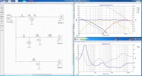
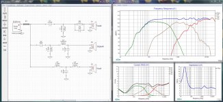
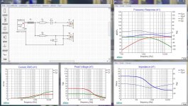
The first thing I usually do after sketching out a possible design is to check it for any big currents that signal wasted energy. Since these currents almost always happen in shunt components I opened a Current window in XSim and had the software chart them for me. (Click "Add Graph" then "More" then "Current") To get more revealing curves in this chart I bumped your amplifier power to 100 watts (nothing to do with your amplifer, just more "chart" to look at).
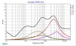
L1 is drawing a serious ton of current right above the cross over point, at 2500 hz. This is very inefficient and poses a heavy load on the amplifer that is sure to cause some heat. The reason this is happening is that C1 is too big, passing in way to much lower frequency energy and L1 is way to small taking that excess energy off the tweeter.
Suggestion try to reduce C1 and increase L1 to tame it down a bit.
C3 in your midrange section is also pulling a lot of current at about 3000hz which is above your mid-tweeter crossover point. There might be a couple of reasons for this including interractions with L2 and L5.
Similarly L3 is drawing a fair bit of current from about 200hz to 1000hz.
Suggestion Try returning C2, L3, L2 and C3 to reduce these currents.
The woofer circuit is only second order and the woofer exhibits some very nasty breakup at abut 4000hz.
Suggestion Consider taking this circuit up to 4th order (electrical) and try to knock the woofer's breakup down a bit more, being cautious not to draw too much current in the process.
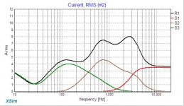
Finally, I added R1 which is just a shorted resistor used to monitor the total current. If you open a second current window and open curves for your drivers and R1 you can see how much current is being wasted.
Overall ... Pretty good for a beginner!
Attachments
Last edited:
I like the R1 suggestion! I've been trying to find wasted power with the power dissipation graph. I'll give these suggestions a try.
I never thought to recenter the graph to see the woofer break up. Thanks!
I never thought to recenter the graph to see the woofer break up. Thanks!
I like the R1 suggestion! I've been trying to find wasted power with the power dissipation graph. I'll give these suggestions a try.
I never thought to recenter the graph to see the woofer break up. Thanks!
You're welcome... when you're ready, you can post a new DXO file and we can try again... Nothing like this ever turns out perfect on the first iteration.
BTW... the forum will up load DXO files directly, no need to zip them.
First 2 issues with XSim:
- turn off the system phase. It really doesn't tell you very much. Instead turn on the phase for all 3 drivers (look in the "Tune" box). Because, in addition to trying to produce a flat FR, you are also trying to align the phase of each respective driver in the region of the xo points.
- once you import your files, still in the "Tune" box, choose to extract minimum phase for all files by clicking 'extract' in the little phase boxes. For the frd files you get an additional box that is asking you to extend the ends of the FR, the 'tails". For the lower tail, just choose a point where the slope becomes more consistent - I chose close to 30Hz for the RS125 - and then choose a slope that matches what you see - I chose 12dB/octave. For the upper tail, do the same - 20kHz is fine and I chose -39dB. Click OK.
It wouldn't hurt to input acoustic center info even if it's just a ballpark figure for now. I can explain how to get the most accurate estimate besides doing it thru measurements tomorrow when I have more time. Try 1" for the mid and 2" for the woofer for now. Leave the tweeter at 0. Again look in the 'Tune' box and input the numbers into the 'mod delay' box.
The next thing to do before you get started in XSim is to have a closer look at your drivers and come up with a xo strategy - what should your xo points be and what should your acoustic slopes be?
In a very general sense you are trying to only use each driver's good stuff and to quiet the bad stuff as much as is necessary. So for this you want to be looking at driver directivity, resonant frequency (most importantly for the tweeter), harmonic distortion (3rd order most importantly) and cone resonances (not the same as Fs, the driver's resonant frequency). Here are 2 well known rules of thumb:
1 - keep the xo frequency below the point at which a driver's FR drops more than 3dB at 45 degrees off-axis. In the case of your 3-way, this is only going to matter for the mid. based on the RS125-8's spec sheet, this looks to me to be somewhere at about 2600Hz.
2 - keep the xo frequency a minimum of 1 octave above a driver's Fs but preferably 2. There is a little flexibility here depending on your choice of xo slope and how loud you intend to play them. Frequently in practice this rule is most important for the tweeter.
So Fs for the mid is 59Hz. One octave is about 120Hz and 2 octaves is 240Hz. For the tweeter, Fs is 710Hz so 1 octave is 1420Hz and 2 octaves is 2840Hz. So putting that info together, target xo points end up around 300Hz (or higher) and about 2700Hz. Don't be too perturbed though if they end up +/- a little bit. Sometimes xo's fall into place naturally at a certain frequency and it's not worth fighting it if they are in the ballpark.
That's probably enough for now. I'll have a little more stuff for you on distortion and cone resonance tomorrow.
Very few of us actually listen at 45 degrees off axis so if you extend the criteria to -6dB you can get a wider spread for the midrange; which may or may not be of benefit.
But I am a near enough good enough sort of builder and don't aim for perfection.
But I am a near enough good enough sort of builder and don't aim for perfection.
Hi jwilhelm,
I have a few questions for you just to get a better lay of the land so to speak.😀
1)Do you plan on adding baffle step compensation during this learning phase? It could add a greater degree of accuracy to the final xover design.
2) Do you plan on taking frequency response measurements or were you just going to measure the TS parameters for arriving at the correct enclosure sizes? I was a little uncertain on this because you mentioned breaking them in. I have heard that Dayton drivers have reliable specifications so you probably can get accurate enough by punching in their TS values in a simulation program like Unibox. I can help you in this area if you like.🙂
3) Do you have experience with some of the available software tools like Response Modeler, FRD Response Blender, or the before mentioned Unibox? Again, I have spent some time with these tools so if you need assistance please let me know.😀
You will will have lots of fun coming up with a xover that meets our design goals. Btw, you are soaring with eagles working with @Douglas Blake.😀
Best Regards,
Rich
Wow ... lots of good stuff.
I will leave this up to @JWillehm to decide how much he can handle... but I think we might get into some information overload if we heap too much on at one time. Lord knows my head is spinning right now. Maybe we can settle on just getting the topology sorted first then add new features and ideas incrementally as we refine the initial design.
It is true that Dayton's specs and driver files are pretty close to reality. So that makes life a bit easier. I've even done successful driver replacements and crossover adjustments based on them, so that's encouraging.
Also, in the initial phases, of trying to rough out frequency and efficiency issues, turning off all phase markers is helpful. In my experience they're more fine tuning than gross topology.
Baffle step can also wait ... I don't think we need to rush into that immediately.
... just some thoughts, trying to provide a smoother learning curve.
Last edited:
@Douglas Blake
I agree with you. It may be way to much to tackle every facet all at once.🙂 Some of the software I mentioned has somewhat of a learning curve. Thank God I had jReave to to essentially take me by the hand and walk me through it when I was at the beginner stage.😀
Take care and be safe,
Rich
I agree with you. It may be way to much to tackle every facet all at once.🙂 Some of the software I mentioned has somewhat of a learning curve. Thank God I had jReave to to essentially take me by the hand and walk me through it when I was at the beginner stage.😀
Take care and be safe,
Rich
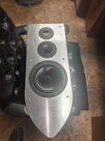
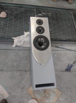
There's lots of good help here! I have the cabinets designed. I used Dayton's measurements to design them. One cabinet is glued up and in primer but needs to go back in the mill for some final drilling and fitting (I use a large CNC mill to cut them). The cabinets will be flat black with polished aluminum front baffles anodized black (requested by the lady that's getting them). I plan to incorporate baffle step compensation into the crossover as well.
Attachments
@jwihelm,
That is some mighty fine craftsmanship you have going on there! Very impressive indeed.😀 She will certainly enjoy listening to them once the project is completed.
Best Regards,
Rich
That is some mighty fine craftsmanship you have going on there! Very impressive indeed.😀 She will certainly enjoy listening to them once the project is completed.
Best Regards,
Rich
Agreed. Whether it is or isn't, this style of crossover needs that decision.1)Do you plan on adding baffle step compensation during this learning phase? It could add a greater degree of accuracy to the final xover design.
I have the cabinets designed.
I Am Impressed ... NICE!
Guess who I'll be calling when I need cabinets.
About those aluminum front panels ... one word: NoRez
It's an anti-resonance padding that will kill any metallic sound for you. I don't know if you can get it from a Canadian source... but Parts Express has it.
Last edited:
Just to keep the confusion going I thought I'd do a Version 2 of my own...
As usual I took the philosophy of making the first part in each chain do the lions share of the work, using shunt parts and following parts mostly for fine tuning.
Note that the frequency response is within a couple of db so it should need only minor tweaks once we have actual driver measurements to work from. Crossovers are at ~500 and ~2500hz. I've not included the group delays and there's no baffle step just yet.
This rendering has a 6 ohm impedance and isn't quite as efficient as I'd like but it should be a good place to start from.
Attachments
Last edited:
Yes, compliments on the cabinets as well.
You will hear some naysayers on the choice of aluminum. Don't listen to them. I also chose an aluminum CNC'd front baffle for my 1st build and the results were fantastic. But I also had concerns about resonance so I applied multiple coats of a damping compound before painting (might have been something like Quietcoat - I'm having a hard time remembering what it was except it was darn expensive). I also think it didn't hurt that I attached them with threaded rods thru to the back baffle which helps to put them under tension, further increasing stiffness and diminishing further resonant behavior. Probably not possible for your design at this point though.
You will hear some naysayers on the choice of aluminum. Don't listen to them. I also chose an aluminum CNC'd front baffle for my 1st build and the results were fantastic. But I also had concerns about resonance so I applied multiple coats of a damping compound before painting (might have been something like Quietcoat - I'm having a hard time remembering what it was except it was darn expensive). I also think it didn't hurt that I attached them with threaded rods thru to the back baffle which helps to put them under tension, further increasing stiffness and diminishing further resonant behavior. Probably not possible for your design at this point though.
Do we need a naming convention?
When I tampered with Jwilhelm's design I incremented the version and stuck my name on it. Do we think that's good enough?
When I tampered with Jwilhelm's design I incremented the version and stuck my name on it. Do we think that's good enough?
I messed around with some of the suggestions for a few hours last night. I made some good improvements before screwing everything up terribly and couldn't get back to anything useful so I'm back to where I started. I was seeing response close to what you have going Doug, before I screwed it all up (software needs a back button, Ctrl Z doesn't work). is that bump in the tweeter response at 16k going to be an issue? I think 6 ohms is a big improvement over 4, efficiency must be much better! I'll have a closer look after work today.
The front baffle or the speaker is 1.5" MDF and fairly well braced. The aluminum panel on the front is milled from 1/2" aluminum. I put just shy of 1/2" fillet on the edge hoping to ease the diffraction a bit. I've machined a pocket into the rear of the aluminum to allow for some space for bonding goop. Undecided weather to use panel bonder or seam sealer to join aluminum to the MDF baffle. Panel bonder is extremely strong but hardens. If there is ever any delamination of the baffle it can rattle. Seam sealer isn't quite as strong but remains pliable for years so no rattle. Both products do a wonderful job of deadening resonances and are designed for heavy constant vibration (heavy truck products).
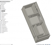
I wasn't looking forward to trying to work with a crossover inside the speaker cabinet so I added a sealed chamber in the rear and am going to mill an aluminum cover for it hopefully large enough to mount the crossover to so a few iterations won't be too painful.
The front baffle or the speaker is 1.5" MDF and fairly well braced. The aluminum panel on the front is milled from 1/2" aluminum. I put just shy of 1/2" fillet on the edge hoping to ease the diffraction a bit. I've machined a pocket into the rear of the aluminum to allow for some space for bonding goop. Undecided weather to use panel bonder or seam sealer to join aluminum to the MDF baffle. Panel bonder is extremely strong but hardens. If there is ever any delamination of the baffle it can rattle. Seam sealer isn't quite as strong but remains pliable for years so no rattle. Both products do a wonderful job of deadening resonances and are designed for heavy constant vibration (heavy truck products).
I wasn't looking forward to trying to work with a crossover inside the speaker cabinet so I added a sealed chamber in the rear and am going to mill an aluminum cover for it hopefully large enough to mount the crossover to so a few iterations won't be too painful.
Attachments
I messed around with some of the suggestions for a few hours last night. I made some good improvements before screwing everything up terribly and couldn't get back to anything useful so I'm back to where I started.
I just keep saving copies as I work... if you notice I changed the file name for my DXO file so it wouldn't clobber yours. Worst case I have copies of both on my system.
is that bump in the tweeter response at 16k going to be an issue?
Hmmmm ... let me see now... a 1 db bump at frequencies so high only a dog can hear it where there is no musical content ... Ummmm.... No? 😉
Despite what some claim, people don't hear tiny defects like that. Our ears just aren't that precise. In general getting a crossover closer than plus or minus 3db is considered to be "close as makes no difference". We should also consider the expense of throwing parts at it and the increased risk of failure that brings. (A good design also considers failure modes)
My friend, I'm very "old school"... I still believe all the old adages like the KISS principle (Keep It Stupidly Simple) and "If it ain't broke, don't fix it"...
I think 6 ohms is a big improvement over 4, efficiency must be much better! I'll have a closer look after work today.
Getting rid of that current bulge in the tweeter circuit helps a lot.
You can safely download the DXO I posted, just make a copy and tamper with the part values all you like. The best way to learn is to change one value at a time and see what effect it has.
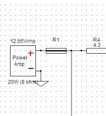
In fact I have this little test jig file (attached) you can mess with to see exactly what the parts themselves do in a circuit. Just take it and tamper with the capacitor values and watch the frequency and current panels to see what a capacitor does, then replace the caps with coils and tamper some more... The take away is that these parts are dumb and their behaviour never changes... The magic is all in how we use them.
I wasn't looking forward to trying to work with a crossover inside the speaker cabinet so I added a sealed chamber in the rear and am going to mill an aluminum cover for it hopefully large enough to mount the crossover to so a few iterations won't be too painful.
Good plan... well thought out.
For what it's worth ... the designs we have so far shouldn't be much bigger than a slice of bread...
Attachments
Last edited:
"One cabinet is glued up and in primer"
What Product are you using for the top coat finish?
I'll likely shoot the cabinet with flattened Imron. The aluminum will be polished and anodized black giving it a piano black finish that beat stainless for accumulating fingerprints!
- Home
- Loudspeakers
- Multi-Way
- Crossover Critique