I guess yes, complex impedances are the keys here....
I really think the complex impedances are playing nasty tricks on the opamp. Any ideas how to control this?
And why on earth does inserting a buffer / voltage follower between the TVC and the filter not solve the problem?
The complex impedances, that are not indicated anywhere. This is why you don't have much chance to control them. There are many parasitic reactances in your circuit, including GND inductances that depend on layout, but your layout is completely unknown. To draw a qualitatively correct schematic knowing layout and connections (cables) are neccessary. Then you can start to play with the values to find the actual root cause.
A photo can tell many things.
Yes.
Yes. It's like the filter opamp can smell the transformer through the buffer.
As you know this is not possible. So there must be an unintended second signal path within the circuit. It can be via
- GND network
- capacitive coupling
- inductive coupling
- misconnection
- power supply rails
- system signal loop
- the combination of above mentioned
- ...
I still see my spike theory as the most likely cause.
Dac's are causing spikes after all.
To see if this is the case, place a 100 Ohm resistor between trafo and point A, and a 33nF cap from A to Gnd.
This creates a 50 Khz filter to attenuate spikes.
I don' t believe in complex impedances or the likes causing problems in this very case.
With a low impedance buffer the problems are still there.
And the problem remains with different types of opamps.
So the opamp itself can also be scrapped from the list, a Fet opamp will not solve the problem.
Hans
Hans,
I don't say your explanation is impossible, but I can see strong problems with it:
Sidenote: Spikes are generated due to parasitic reactances.
Relevant info: data dependent spikes (known as glitches) has very low energy, because if not, then the whole DAC is a crap. Second: in a good DAC therefore random glitches are blanked, this way replaced by uniform, periodic (sample freq) impulses that are not audible. And these kind of pulses clearly can't produce the experienced type of distortion.
Question: How can you explain the experienced dependency on transformer tap setting? Will the spike be bigger at low volume setting? If yes, then how else than due to (changed) parasitic reactances?
My opinion: I can hardly imagine an impulse that
- has negligible average charge not to completely ruin audio performance by itself, and
- has such high and asymmetric rise and fall slope that can overload OPA this much.
And after a glitche OPA returns to normal operation, settling back very fast. No, the waveform seen is extremely hard to explain with glitches.
The buffer doesn't solve layout problems, nor changes parasitics.
Be careful! The OPA alone is not the cause, this is proven, but with 100% certainity it is the main part of the effect chain, this is perfectly proven by the measurements. Therefore you can never tell a different OPA cant ease the problem, and definitely cant rule out from the list. Your own explanation relies on it strongly also.
I don't say your explanation is impossible, but I can see strong problems with it:
Sidenote: Spikes are generated due to parasitic reactances.
Relevant info: data dependent spikes (known as glitches) has very low energy, because if not, then the whole DAC is a crap. Second: in a good DAC therefore random glitches are blanked, this way replaced by uniform, periodic (sample freq) impulses that are not audible. And these kind of pulses clearly can't produce the experienced type of distortion.
Question: How can you explain the experienced dependency on transformer tap setting? Will the spike be bigger at low volume setting? If yes, then how else than due to (changed) parasitic reactances?
My opinion: I can hardly imagine an impulse that
- has negligible average charge not to completely ruin audio performance by itself, and
- has such high and asymmetric rise and fall slope that can overload OPA this much.
And after a glitche OPA returns to normal operation, settling back very fast. No, the waveform seen is extremely hard to explain with glitches.
With a low impedance buffer the problems are still there.
The buffer doesn't solve layout problems, nor changes parasitics.
So the opamp itself can also be scrapped from the list, a Fet opamp will not solve the problem
Be careful! The OPA alone is not the cause, this is proven, but with 100% certainity it is the main part of the effect chain, this is perfectly proven by the measurements. Therefore you can never tell a different OPA cant ease the problem, and definitely cant rule out from the list. Your own explanation relies on it strongly also.
Last edited:
Wow, lots of questions and suggestions here! Thanks!
I'll try to keep things together here...
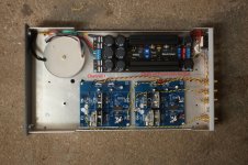
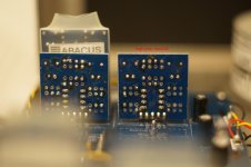
I attached a few pictures of the xover (whole board, and details of the little high-pass module where the headaches seem to start).
Hmm, before I rush and do something silly: what resistor / capacitor values are you thinking of for the pi / T pad or the Zobel network? Which "input" are you referring to (input of the filter, input of the opamp, input of the TVC)?
Hmmmmmmm. I believe the unsed OPA is not "deactivated". The inputs might be connected to the opamp in the Sallen Key filter; I believe I remember I've seen very similar signals at the unused opamp. Could there be an interference between the two opamps in the IC?
The data I've shown so far were taken with a soundcard. I do have an old oscilloscope, but it does not have a memory function. Just triggering on the sine smears out the display of the low voltage signal due to the noise, and things become invisible.
I've tried different sine frequencies (250 Hz to 3 kHz or so). The pips remained on the wave peaks.
Ok, I'll try the RC filter between the TVC and the xover (but I need some time to get this done).
But what do you mean by "DACs are causing spikes after all"? What kind of spikes would this be, and why?
I'll try to keep things together here...
I think we haven't seen a picture of the situation yet ?! Would help just like gathering data.
I attached a few pictures of the xover (whole board, and details of the little high-pass module where the headaches seem to start).
This smells like parasitic oscillation. What happens if you insert a pi or T attenuation pad between the TVC and the filter? What happens if you insert a Zobel network at the input?
Hmm, before I rush and do something silly: what resistor / capacitor values are you thinking of for the pi / T pad or the Zobel network? Which "input" are you referring to (input of the filter, input of the opamp, input of the TVC)?
the unused OPAs also can oscillate if not deactivated correctly.
Hmmmmmmm. I believe the unsed OPA is not "deactivated". The inputs might be connected to the opamp in the Sallen Key filter; I believe I remember I've seen very similar signals at the unused opamp. Could there be an interference between the two opamps in the IC?
A high speed oscilloscope is needed to check oscillation.
The data I've shown so far were taken with a soundcard. I do have an old oscilloscope, but it does not have a memory function. Just triggering on the sine smears out the display of the low voltage signal due to the noise, and things become invisible.
when you change the input frequency, does the 'pip' remain on the sine wave peaks?
I've tried different sine frequencies (250 Hz to 3 kHz or so). The pips remained on the wave peaks.
I still see my spike theory as the most likely cause.
Dac's are causing spikes after all.
To see if this is the case, place a 100 Ohm resistor between trafo and point A, and a 33nF cap from A to Gnd. This creates a 50 Khz filter to attenuate spikes.
Ok, I'll try the RC filter between the TVC and the xover (but I need some time to get this done).
But what do you mean by "DACs are causing spikes after all"? What kind of spikes would this be, and why?
Attachments

Voltage supply is +/- 15 VDC. Decoupling capacitors next the the opamp are 47uF electrolytic and a small ceramic.
I hope you mean these are on both rails to GND.
I do have an old oscilloscope, but it does not have a memory function. Just triggering on the sine smears out the display of the low voltage signal due to the noise, and things become invisible.
An oscillation that can cause this much distortion must have significant amplitude. There cannot be visible noise on an analog scope unless scope is damaged. If something smears out the display, then it's most probably the oscillation itself. An analog scope gives much detailed information about linear amplifiers usually than a (not high-end) DSO, just need some experience to set and understand. I suggest you to measure and take photo whatever you see.
An oscillation that can cause this much distortion must have significant amplitude. There cannot be visible noise on an analog scope unless scope is damaged. If something smears out the display, then it's most probably the oscillation itself. An analog scope gives much detailed information about linear amplifiers usually than a (not high-end) DSO, just need some experience to set and understand. I suggest you to measure and take photo whatever you see.
My old scope won't store a snapshot. When it triggers to the test signal it will override the display at the rate of the vertical resolution. With the small signals used here (mV range), noise smears out the display to a level where it becomes useless.
Spikes may be generated at the start of each clock cycle when converting the next digital value into an analog signal.Ok, I'll try the RC filter between the TVC and the xover (but I need some time to get this done).
But what do you mean by "DACs are causing spikes after all"? What kind of spikes would this be, and why?
Depending on the type of DAC and the type of filter that should suppress the high frequency content, spikes may occur.
Especially when the PCB layout is not optimal this can result in the sort of problems that you are facing due to parasitic effects.
In posting #1 you have mentioned two things, reinforcing my feeling that the DAC is causing the trouble:
1) a very long cable between Dac and filter reduced your problem, and
2) when muting your high pass filter into a low pass filter problems are also gone.
Both steps filter high frequencies.
According to Pafi a DAC that produces glitches is crap. I won't go that far, but I have the feeling your DAC is not yet as it should be.
When I'm right it is a NOS dac, producing enormous amounts of High Frequency content, and last but not least it has not even a HF filter in its standard form.
There is a provision for an optional cap of between 4.7 nF and 10 nF.
Did you place this cap or not ?
This seems to be the the least that should be done.
As a matter of fact, a NOS DAC without output filter when outputting 400Hz, also generates quite some Fs +/- 400Hz, 2Fs +/- 400Hz etc.
Hans
Many UK designed CDP used a 5pole Butterworth or Bessel filter as part of the analogue output stage.
This was often criticised by the audio press for rolling off the treble a bit compared to the much steeper cheby filters used by the Japanese and others.
But all had filtering to reduce the HF non audio crap that is generated by the D to A stages.
This was often criticised by the audio press for rolling off the treble a bit compared to the much steeper cheby filters used by the Japanese and others.
But all had filtering to reduce the HF non audio crap that is generated by the D to A stages.
I have no resistor values in mind. I don't even have an attenuation figure in mind. Up to you to choose appropriate ones. The point is that this provides something different from a series resistor or a shunt resistor, both of which you have already tried.mbrennwa said:Hmm, before I rush and do something silly: what resistor / capacitor values are you thinking of for the pi / T pad or the Zobel network? Which "input" are you referring to (input of the filter, input of the opamp, input of the TVC)?
By 'input' I mean the point where the TVC output meets the filter input.
Inserting a buffer might not clear the fault if the buffer has the same problem as the filter. As we don't yet know what that problem is, we can't say that the buffer does not have it too.
One thing to try: modify the filter so the feedback comes from a 6dB attenuator at the output. This moves the opamp away from the unity gain region.
My old scope won't store a snapshot. When it triggers to the test signal it will override the display at the rate of the vertical resolution. With the small signals used here (mV range), noise smears out the display to a level where it becomes useless.
Don't need a stored snapshot. If you can trigger to the test signal, then it cannot be useless. Even if you can't trigger, you can tune the vertical freq to be in synchron more-or less with signal, and take a photo. Trust me, this is the easiest way to check if oscillation is occured or not. You don't want to ignore the possibility of oscillation do you?
You can also increase amplitude. Or does it eliminate the distortion?
Is there any DC on the output of the DAC? DC will cause transformer non-linearity.
DAC's in parallel -- you might want to put some resistance on each of the DAC outputs.
DAC's in parallel -- you might want to put some resistance on each of the DAC outputs.
I made a mistake, I wrote vertical freq, but I ment horisontal of course.
Jack, please read the thread! No DC, and not the trafo distorts the signal.
Jack, please read the thread! No DC, and not the trafo distorts the signal.
I made a mistake, I wrote vertical freq, but I ment horisontal of course.
Jack, please read the thread! No DC, and not the trafo distorts the signal.
Sorry.
TI reference design has a low pass filter after the IV conversion, or uses an NE5534 with low Zin (820R||2200pF) for the same purpose.
OK, I see your point. Note that the TVC also acts as a low pass filter. But I will still try the RC lowpass you suggested (once I am back from hospital).Spikes may be generated at the start of each clock cycle when converting the next digital value into an analog signal.
Depending on the type of DAC and the type of filter that should suppress the high frequency content, spikes may occur.
Especially when the PCB layout is not optimal this can result in the sort of problems that you are facing due to parasitic effects.
In posting #1 you have mentioned two things, reinforcing my feeling that the DAC is causing the trouble:
1) a very long cable between Dac and filter reduced your problem, and
2) when muting your high pass filter into a low pass filter problems are also gone.
Both steps filter high frequencies.
According to Pafi a DAC that produces glitches is crap. I won't go that far, but I have the feeling your DAC is not yet as it should be.
When I'm right it is a NOS dac, producing enormous amounts of High Frequency content, and last but not least it has not even a HF filter in its standard form.
There is a provision for an optional cap of between 4.7 nF and 10 nF.
Did you place this cap or not ?
This seems to be the the least that should be done.
As a matter of fact, a NOS DAC without output filter when outputting 400Hz, also generates quite some Fs +/- 400Hz, 2Fs +/- 400Hz etc.
Hans
OK, I see your point. Note that the TVC also acts as a low pass filter. But I will still try the RC lowpass you suggested (once I am back from hospital).
And don't forget to place the two optional 10nF caps on your NOSDac.
It's better to do this as the first step,
See Picture

Hans
And don't forget to place the two optional 10nF caps on your NOSDac.
It's better to do this as the first step,
See Picture
View attachment 580655
Hans
THANKS for the attachment, now I understand what filter caps you're referring to. I have an older DDDAC board that does not have the optional caps, so I was a bit confused. But I can still add them and see what it does.
Mbrennwa,
There are a lot of possibly problematic point in your system. For example you use unshielded signal cables. With unbalanced signal this is a known source of unwanted signal coupling especially at high freq. But many things are still invisible. Connections to other elements in the system. This is essential, since you experienced the distortion strongly depends on the other elements and connections too.
The entry key to engineering is an oscilloscope. You have it. Use it! It gives much more information then building a random filter and seeing if distortion changed or not.
But you also have a simple way to determine if DAC was responsible for HF content causing distortion: insert signal from generator to output of DAC (=primary of trafo). This way you can separate the effect of DAC from effect of transformer.
ETC...
you use unshielded signal cables.
I have tried with shielded cables before, didn't make a difference.
- Status
- Not open for further replies.
- Home
- Source & Line
- Analog Line Level
- Crazy distortion problem with transformer and active filter (opamp / Sallen Key)