Hey ! That's why my speakers are so FAST ! No, wait, that's how I do the F.A.S.T. way . Indeed they employ a series crossover ...🙄An allpass filter has flat frequency response but shapes the phase response. It is there for a reason, go ahead and take it out who knows if it will sound better or not. You're so determined to "fix" this design that I'm sure to your ears it will sound better no matter what.
Why don't you just put a cap to the tweeter and an inductor to the woofer, no wire the woofer directly it will be FASTER that way.

So, an allpass filter gives delay, as phase carries the 'time' information bit.
And the guy(s )that did the B&W crossover and certified it for each speaker had certainly included that in the design stage. At that frequencies above 1 KHz = Lambda = 3,8 cm you change the position at 3.8 / 2 and you're out of phase 180 °. So it don't really matters BUT at crossover frequency when analyzing the loudspeaker(s) system a 180° shift means destructive interference. That's what happens when you change phase to the tweeter, or any speaker that has another one speaker nearby
Pete, you have been quite helpful, I'm sure you didn't mean that like it sounded. No modifications to have been made crossover points, no mods to slopes no mods to amplitudes have taken place here. I have only removed the tweeter protection and the odd load LCR circuit after verifying it did not affect FR. The only remaining mod I wish to test is the small delay line which is probably there because the speaker is a floor-stander as *you* have clued me into. In fact your posts have been very, very informative. I do know how to extrapolate info. Bear in mind I am no casual listener nor a golden ear audiophile. I am a professional whose mistakes, should I make them, will bear direct financial consequences. If I do something stupid, I will hear it and undo it, I don't play those personal mind games I'll leave that for "cable men" @ "Stereophile" and TAS. My man? Peter Aczel God bless him.
FYI I have several very fine reference speakers in several rooms. This is a very good idea for mixing, as opposed to mastering. Long and short, I will hear pretty quick if I goof.up and I would not change the basic nature
I was teasing you to try and help you get some perspective. You're doing a good job with this.
There is a simple analysis that you can do to better understand that network. At the lowest freq, DC, inductors are shorts and caps are open, note that the tweeter is connected to the network with one polarity. At the highest freq caps are shorts and inductors are open note the opposite driver polarity connection for the tweeter. The network flips the phase 180 deg from DC to max freq.
My concern with removing the network is that the best listening axis might end up pointing nearly straight up, or down, who knows? Some analysis is required.
My concern with removing the network is that the best listening axis might end up pointing nearly straight up, or down, who knows? Some analysis is required.
Last edited:
Yessss........Both speakers sound *identical* now, and oddly enough, I do think they sound a bit nicer above the vertical axis while on the floor. I wonder if this has anything to do with that delay?.......bwhaaahaaaahaaaaahaaa........just kidding. They might sound a db or two lower-mid-bass heavy above 100hz though even near field. I wonder if I'm hearing the removal of those LCR's? It did NOT show up at all in the warbles, probably it is just in the design and when I raise them in the other room it will go away.
Seriously, though very nice imaging, always did like the older tweeter in all B&W's instead of the later metal one, never heard the diamond one, and probably won't anyway.
Most SS amps have a very low source impedance so you should not hear any difference with the LCRs. You might hear a difference when you drive the amp real hard and it strains to provide enough current, then those networks might help avoid triggering the amp current limiters by improving the load factor. They are similar to power factor correction in power supplies.
If you want to hear the difference put one ohm 10 or 20W in series with the amp, then you might hear a very minor difference. Also, you have to use material that hits the freq range of interest. I suggest a noise source since you'll hear a change in the color of the noise. You need to hear the frequencies altered as compared to something else such as the mid band. But don't drive it real hard with noise since it provides constant power to the tweeter and might blow it.
These speakers are sounding bright against other great refs in the same room. I have only removed the lcr impedence circuit at input, cleaned out / replaced new ferrofluid, defeated the protection and recapped c4 c5 with np electros? WTH? They are brighter by far than the 801s, that should not be so. Should I try different caps on c4 c5, the rest except for the bypassed lcrs on input are indestructible giant caps.?
rest except for the bypassed lcrs on input are indestructible giant caps.?Btw, I have *not* bypassed the LC allpass delay on the tweeters.
I am going to try different brands of 20uf electros on C3 I suspect the esr is changing the mid range xover here. Does that sound like reasonable path here?
I am going to try different brands of 20uf electros on C3 I suspect the esr is changing the mid range xover here. Does that sound like reasonable path here?
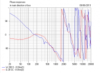
I just spent an hour modelling this speaker. The tweeter delay circuit is rather neat actually. It effectively recesses the tweeter about 3.5cms which really lines it up nicely with an 8" woofer on the 3kHz crossover. The tweeter wires in phase AFAIK.
I shall make a mental note of the circuit. 🙂
If the tweeter is too bright, guessing it is a 4 ohm jobbie, you might put a 1-1.5 ohm 10Watt wirewound at the input to the treble filter. Should drop it about 3dB, and get more of a BBC slope.
I shall make a mental note of the circuit. 🙂
If the tweeter is too bright, guessing it is a 4 ohm jobbie, you might put a 1-1.5 ohm 10Watt wirewound at the input to the treble filter. Should drop it about 3dB, and get more of a BBC slope.
Thanks ., Yeah I figured that out about the delay. Makes perfect sense because these are essentially the prototype for the B&w ones that did exactly that, they moved the tweeter physically back. What does not make sense at all is the over
brightness . These are out of spec somewhere imo.
brightness . These are out of spec somewhere imo.
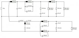
I won't repost the schematic since we are about to turn a page anyway, but C1 and C2 on the bass filter must be very critical if deteriorated. Treble shunt R4 and L4 would muck things up if they went O/C too.
C3 and C4 on the Zobels won't be very critical IMO.
C3 and C4 on the Zobels won't be very critical IMO.
Note that older 801s can loose more than 10 dB of tweeter output due to aging of the dome material:
AudioKarma.org Home Audio Stereo Discussion Forums - View Single Post - My B&W 801 Restoration project.
AudioKarma.org Home Audio Stereo Discussion Forums - View Single Post - My B&W 801 Restoration project.
Pete, most interesting developments studying your B&W Matrix 3...😎
Uploaded with ImageShack.us
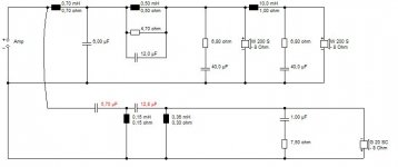
The woofers are 8" polypropylene types, and the tweeter is probably 4 ohm soft dome. As remarked earlier, the lower woofer just adds a bit of bottom. It's essentially a two way at heart. B&W claim a nominally flat 4 ohm impedance across the range, so it's valve friendly.
This is a top class speaker of the eighties I reckon. Very well time aligned. BUT WE CAN DO BETTER these days. 😀
I could simplify the bass filter to second order coil plus series resistor and capacitor, and add a tank notch across the coil at 7kHz, but what is extremely interesting to me, is that the time delay circuit on the treble can be replaced by a 4th order filter and get almost identical alignment. 8" bass plus 1" tweeter on a flat baffle is a stinker of a problem that has beaten me for years because the time alignment on a deep bass unit goes horribly wrong . Suddenly we know what to do with it. Thanks, man, I'm excited! 😎
(BTW, the modelling isn't exact, because I've used a 8 ohm tweeter, but the principle applies! Tweakers note, you add input resistance to the treble filter to attenuate the treble. )
An externally hosted image should be here but it was not working when we last tested it.
Uploaded with ImageShack.us
The woofers are 8" polypropylene types, and the tweeter is probably 4 ohm soft dome. As remarked earlier, the lower woofer just adds a bit of bottom. It's essentially a two way at heart. B&W claim a nominally flat 4 ohm impedance across the range, so it's valve friendly.
This is a top class speaker of the eighties I reckon. Very well time aligned. BUT WE CAN DO BETTER these days. 😀
I could simplify the bass filter to second order coil plus series resistor and capacitor, and add a tank notch across the coil at 7kHz, but what is extremely interesting to me, is that the time delay circuit on the treble can be replaced by a 4th order filter and get almost identical alignment. 8" bass plus 1" tweeter on a flat baffle is a stinker of a problem that has beaten me for years because the time alignment on a deep bass unit goes horribly wrong . Suddenly we know what to do with it. Thanks, man, I'm excited! 😎
(BTW, the modelling isn't exact, because I've used a 8 ohm tweeter, but the principle applies! Tweakers note, you add input resistance to the treble filter to attenuate the treble. )
Attachments

Last edited:
These tweeters are hot. Something is wrong. All the caps that really count are polys. All 5 of the diaphragms I have dcr around 6.1 ohms, so no variation there. As I said I have eliminated only the protection, and the two impedance leveling lcrs on input. Maddening. Unless I have the wrong amount of ferrofluid, but this seemed to sort itself out as the coils,
would not drop in till I incrementally wicked enough out. I want imagine enough underdamping to make them this much too bright. what else could be going on here? This would be easier to understand if it were too low of a tweeter level. Weird. they are so close to being ideal. This is against all of my refs, not just 801s. Something is up here. How can a tweeter level get jacked up without a cap going bad? And equally in both speakers to boot?
would not drop in till I incrementally wicked enough out. I want imagine enough underdamping to make them this much too bright. what else could be going on here? This would be easier to understand if it were too low of a tweeter level. Weird. they are so close to being ideal. This is against all of my refs, not just 801s. Something is up here. How can a tweeter level get jacked up without a cap going bad? And equally in both speakers to boot?
Last edited:
Would be nice if the Craigslist predator would have given me a set with the crossovers that came with the units, but these replacements are the right ones from only a few months later.
Could any of the 20uf electrolytics cause the highs to not be rolled off properly in the mid/bass unit, therefore causing the perception of "too much tweeter"? And where would you all say the crossover was here anyway? 3.5 maybe? Look like I'm going to wind up measuring and understanding more than I intended to, but the fact is all of these older, more affordable and in many cases better reference monitors need maintaining
Pete, your unpaid crossover consultant (me) has given you the modelling albeit with different Visaton drivers. 😀
It's a 3kHz crossover. Given I now know these are 8 ohm polyamide tweeters (@ 6 ohm DC), I would suggest you add a 3.3R 7 or 10W wirewound at the input to the treble filter. That will quieten down the tweeters about 4dB which should do the business towards a more civilised brightness level.
I'd doubt if the small bass Zobel capacitor mod has changed things much. I'd guess these are just your usual speakers balanced toward an irritating showroom brightness.
Looks like MKT (polyester, Harbeth-style) capacitors to me, but could be MKP.
Attachments

Well, what you know, C1 had been replaced with waayyy wrong value on both of the replacement crossover, moreover they were a newer metalized type. Put in some temporary 6uf electrolytics and they sound fine. Thank you all for pointing me to C1.
- Status
- Not open for further replies.
- Home
- Loudspeakers
- Multi-Way
- Could a kind soul please break down this horrid Xover