A bit OT but sort of not...........
"The Hammond chorus/vibrato circuit has become famous in its own right, with organs that have a “real” scanner-based vibrato being more valuable than those without. So what is this circuit and how does it work?
In short, it is a 9 stage delay line. The delay is produced using LC phase shift circuits. It can produce only a very short delay of around 1mS . A variable delay is required for vibrato or chorus, and this is generated by the rotating scanner arm picking up signals from each stage of the delay in turn. Because of the way this is done (air-gap capacitor, essentially) the effect is a fade between one stage and the next. The scanner is set to scan each tap from 1 through to 9 and then back again 9 to 1. This is equivalent to a triangle wave modulation of the delay time. The complete cycle, from 1 to 9 and back, is 16 steps"
Oh what a difference a millisecond or two can make.
Last edited:
I'm also guessing the 63uf electrolyte could be affecting high-mids? I have found a value of 65uf available.
Hi Steve, Mosquito
Thanks for highlighting L5, L6, C7, C8. Learned something new. Never used delay before.
Mosquito
What software is that ? Looks interesting.
Thanks for highlighting L5, L6, C7, C8. Learned something new. Never used delay before.
Mosquito
What software is that ? Looks interesting.
If intending for serious work, given description of age and state of butchery, speakers need to be measured and checked for how well matched they are.
Highly questionable given choice of fully active monitors available.
Highly questionable given choice of fully active monitors available.
This is AFW Pro, a software from Technipress, publisher of the italian AudioReview magazine. It cost some euros, is not expensive at all, but is not free.Mosquito
What software is that ? Looks interesting.
Audio For Windows
Cheers
J.
If intending for serious work, given description of age and state of butchery, speakers need to be measured and checked for how well matched they are.
Highly questionable given choice of fully active monitors available.
My face is a highly questionable given the choice that the people in Hollywood have available, but it is one that I do serious work with and I've decided to measure and check it. (-:
Seriously, I have several great refs already and but these are ideal for the room I'm putting them in and besides that I just f'n like getting great speakers back to spec 😀
Two last serious questions for you great guys and I shall do 12 John Bowers' 24 John Dunlavy's, 2 1/2 Bob Ludwigs and go forth and sin no more.
The LCR notch that includes 63uf electrolytic, what frequency is it centered at?
The LCR notch that includes 600uf electrolytic, what frequency is it centered at?
Ok, another question. Since I cant find the exact values of the 600uf and 63uf, may I parallel some electrolytics without messing up the designed in ESR, or would I be more accurate just going to the closest value, in the case of the 63uf, say 60uf or 68uf. or would I be better off say making a 60uf with whatever adds to it, keeping in mind the guys @ b&w did value in the ESR in these xovers?
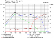
Pete, I just ran some sims of this circuit in Visaton Boxsim.
It's a shocker! 😀
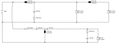
The two weird LCRs at the woofer input really don't do ANYTHING with a transistor amp. 19mH and 600uF must be some sort of woofer Fs correction, but only works with a valve amp...
I simplified the B&W circuit down to the second circuit. Quite honestly the second low woofer connected by the 10mH does nothing except add a huge peak at 60Hz. I'd disconnect it. The time delay in the tweeter is plain stoopid, IMO.
It's a shocker! 😀
The two weird LCRs at the woofer input really don't do ANYTHING with a transistor amp. 19mH and 600uF must be some sort of woofer Fs correction, but only works with a valve amp...
I simplified the B&W circuit down to the second circuit. Quite honestly the second low woofer connected by the 10mH does nothing except add a huge peak at 60Hz. I'd disconnect it. The time delay in the tweeter is plain stoopid, IMO.
Attachments

Whoa! that's a lot of info! The thing is these units did measure flat 2/1/2db from 70hz up and came with a very decent plot, well measured. I am all for removing the LCR stuff that you feel is for tube loads as long as you are certain it will not affect final FR. As far as the time delay circuit on the tweeter, I would not know what to do with it, so I might be inclined to let it stay unless you feel it is detrimental. At this point then, Here is what I plan.
1. Remove the 600uf and 63uf LCR notch/impendence/tubeload circuits
2.Recap all the 20uf electros
3.disable tweeter protection.
If you really feel I should bypass the delay circuit on the tweeter, could you tell me how to do so mechanically with jumpers or lifting legs? Many thanks for this, I was sort of expecting that this crossover was different than most of the other B&W units. It is true that they went to far simpler crossovers in speakers using these identical drivers. Soooo.the two LCR's at the input..100% a .. a concession to tube amps?..... yuckk..
Last edited:
In answer to Post #27,t.he notch frequencies for the L.F. series networks are approx. 80 Hz and 46.5 Hz .It would be interesting to compare results,with and without them in circuit,as while initially a flattening of impedance at resonant frequencies and extra dampening occurs,there is no provision to overcome variation of those set freq,s with program level and other effects.
In answer to Post #27,t.he notch frequencies for the L.F. series networks are approx. 80 Hz and 46.5 Hz .It would be interesting to compare results,with and without them in circuit,as while initially a flattening of impedance at resonant frequencies and extra dampening occurs,there is no provision to overcome variation of those set freq,s with program level and other effects.
Thank you VaNarn.If I am understanding System7 correctly, these notches will *never* come into play or even be "seen" by a modern solid state amp at all, in no way affect FR in that situation, and can there for be safely eliminated without audible consequence?
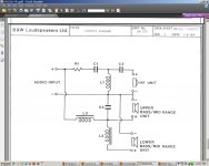
Ok, look at this, the crossover for the B&W DM220 a similar speaker with nearly the same tweeter (smaller mag) non matrix bracing, paper cone woofers @16 ohms. A bit simpler is it not?
Attachments
Last edited:
I've gotta 'fess up that I made a complete hash of the box volume in my sim, Pete....😱
I was using 10L per woofer. I don't know quite how that happened. 🙄
If I toss in about 40L per woofer, the bass peak is less horrid. 😎
Nevertheless, my simple circuit works almost exactly like the original:
http://www.diyaudio.com/forums/multi-way/236806-could-kind-soul-please-break-down-horrid-xover-3.html#post3509689
Second order woofer, third order tweet. Your B&W circuit is way too complicated. All those Zobels and impedance correction and time alignment. At heart you have a simple two way. I could do better too. I'd do a 5KHz notch and get it rockin and rollin. 😀
I would prefer to compare the effects of the notch cct's,in and out of circuit,to test if there is merit in their inclusion.I would think that B&W would have designed the speakers with high powered solid state amplifiers in mind,given the lowish sensitivity and the use of protection cct,s.The three way xover from 1984 is basic and is what is expected in the lesser models from B&W.
I don't want to design a new crossover though, Can I safely remove both notch LCRs, remove the protection and recap all of the 20uf electros without changing FR? I think that would be all I need to do here.
I would prefer to compare the effects of the notch cct's,in and out of circuit,to test if there is merit in their inclusion.I would think that B&W would have designed the speakers with high powered solid state amplifiers in mind,given the lowish sensitivity and the use of protection cct,s.The three way xover from 1984 is basic and is what is expected in the lesser models from B&W.
Thanks, that is easy enough to do, Ill just play some warble tones from 30 to 100 while lifting a leg of the cap,
So far so great, I have one finished. system7: You sir win the golden pickle. There was no audible difference whatsoever in the low end FR after removing the two LCR circuits on the input and listening to a 40 to 100hz warble tone while connecting and un-connecting the circuits.. I did remove the circuits, recapped the 2 remaining 20uf electros, and "one legged" the diodesD1 and D2. What do I think I hear? Well I know I am hearing a very flat and *clear* sounding speaker, In short, they sound very, very much like the 801's only with less low bass. If the other one sounds the same then this has been a complete success. The only thing else I may do is bypass that weird delay circuit on the tweeter if you guys think there may be any sonic benefit. I am thinking it might be benign or beneficial based on just on this listen and trust me when I say I do listen critically. (-:
Hi, At Your place, I will carefully listen to the speakers with, the time delay circuit, and without. On my simulator this cell, if terminated on a 6.5 ohm load , features a 158uS delay, and this will be very noticeable to the ear: Now, I do not have a clue about the specs of the B&W driver units, nor the effective cell behaviour on them, but Sure they put it there for a reason.
- Status
- Not open for further replies.
- Home
- Loudspeakers
- Multi-Way
- Could a kind soul please break down this horrid Xover