Seems correct. I did some back-of-the-envelope calculations for a TZ20 output stage operating at 300V with a 100k + 20k feedback network, indicating quiescent point at around -20V and a +-80V voltage swing.P-channel mosfet bias will probably still work out to a negative voltage, but far less so.
I have two pairs of speakers in my hobby room, one smaller pair that prefers amps with a medium to high damping factor and a pair of big BR/horn hybrids that sounds better with low DF amps. This opens up for some cretive amp building, including amps with adjustable NFB to tune the output impedance to match both pairs or speakers.
I've been on a little thorium shopping spree lately with the ambition to build an amp with adjustable filament and HT supplies and multi-tapped OPTs to employ a wide range of different high mu triodes as output tubes. Now I'm leaning more towards splitting this project into two different amps, one smaller for T20/TZ20 tubes and a bigger one for the fatter bottles.
Philosphically. the smaller one could be allowed to be a bit of an FX box with moderate amounts of feedback while the larger amp probably would benefit from more feedback to flatten out the differences between the larger selection of output tubes.

A question: How much would a choke loaded (instead of CCS or resistor loaded) source/cathode follower driver stage interfere with the output anode to input cathode feedback? I assume the chokes will introduce some phase shifts that will cause trouble at higher feedback levels.
I'm currently listening to a prototype using T20 triodes in class A2 (6SN7 input stages RC coupled to choke loaded 25E5 cathode followers, direct coupled to the T20 grids). The only NFB in the prototype is ~3dB of cathode feedback from the 16R taps on the output transformers, enough to make the amp sound more than half decent but the damping factor is still a bit on the low side.
My lack of modern test equipment stops me from messing around with high NFB circuits but perhaps it would be doable to change the input tube to something with a bit more gain and then add a little bit of output plate to input cathode feedback, perhaps 6dBs or so just to tighten up the bass a bit more?
Those are great questions and I'm not sure I really know the answers, but 6dB isn't too much feedback so it might be pretty safe. I'm running somewhere near 35dB right now and I get no oscillatory behaviors with any loads that I tested.
Is there a reason you went with the chokes? Was it to avoid a negative rail?
Is there a reason you went with the chokes? Was it to avoid a negative rail?
Typically the parasitic capacitance of a choke will be rather unsubstantial compared to the miller capacitance of a medium/high mu transmitting triode.
I guess the only way to know for sure is to try it. Replacing the input tubes and adding feedback resistors should be easy enough, and even my old `scope shoould be able to tell if anything dramatic happens. I once got severe oscillations in a test circuit with an 808 and some high gm driver tube, it was easily spotted as the 808 plate suddenly went from dull red to bright orange and everything started to make crackling sounds... 😀Those are great questions and I'm not sure I really know the answers, but 6dB isn't too much feedback so it might be pretty safe. I'm running somewhere near 35dB right now and I get no oscillatory behaviors with any loads that I tested.
Is there a reason you went with the chokes? Was it to avoid a negative rail?
Sort of, yes. The easiest way to make a driver stage with a delayed soft start was to use a choke loaded indirectly heated cathode follower.
As I'm using SS diodes in the power supply (+500V and +250V from a 180-0-180VAC transformer) I had to take some measures to make life as easy as possible for the output tubes during startup. The best I could come up with without timer circuits etc. was a choke loaded cathode follower where the cold end of the choke connects to a negative low voltage rail and the CF tube has a thermistor in series with its heater to add some extra delay. This way, the output tubes are biased into complete cutoff until their filaments have reached their full emission capacity.
Things get a bit more complicated as I intend to build this amp to fit three different output tubes with different bias requirements (+23V for TZ20, +12V for T20 and around 0V for 8025A), the solution was to use a few spare heater windings to make a "ladder" of negative voltages available. This way the voltage drop through the choke and thus the idle current through the CF can be kept fairly constant.
A conceptual drawing of the driver/output stage:

As mentioned, I'm already quite impressed by the sound from the prototype. A bit "woolly" in the bass but slightly more "civilized" than my 808 SET.
I could build it as is, with a different input stage and a little bit of extra feedback, or I could take a completely different route: CCS loaded mosfet followers as grid drivers and 24A globe bottles as input tubes, operating as tetrodes with feedback from output anodes to input cathodes.
I have a few globe 24As (even a few blue Arcturus ones) that make a great visual match to the output tubes but their technical merits are questionable and getting rid of the IDH CF driver would complicate things a bit regarding the startup sequence.

Last edited:
In the beginning, I was kind of scared of the high levels of feedback, so I just started low and worked my way up.
I started with a resistive load on the pentode input stage, which didn't produce too much gain and therefore not much feedback. When I went to the CCS load on the input stage I put resistors in parallel until I tried running with just the CCS. Nothing bad ever happened. The feedback loop is pretty short.
Edit: I love the idea of using an old globe tube like the 24A in the input.
Last edited:
The Corona topology is definitely brilliant, a clever way to make good use of otherwise less useful power tubes. My objectives are a bit different but the topology and the information in this thread is still very inspirational.
The perfect solution for me would be an amp with adjustable feedback (or adjustable output impedance, to be more specific) since I have two pairs of speakers in my hobby room with different requirements re. damping factor.
Since my OPTs have a few taps on the primary windings (8k, 5k and 33% UL) I could experiment with taking the NFB from different taps without upsetting the DC conditions.
Yeah, the primary taps might just be the key to accomplishing your goal of variable damping without messing up the input stage DC conditions.
Yes, using the taps would be an elegant solution assuming they all have sufficient bandwidth. Practical tests are called for here. Being able to add up to maybe 6 or 9dBs of extra feedback in a few steps beyond the 3dBs of CFB would be great, with the ability to connect the NFB resistor to B+ for zero extra feedback.
Using a rotary switch would be tempting but too dangerous at 450VDc + signal, some kind of screw terminal should work.
And yes, using the old globe tubes are very tempting for aesthetic reasons. Sadly, they are rare and expensive and technologically inferior to more "modern" tubes. The 24s makes decent triodes with barely enough gain for input stage duty assuming CCS/gyrator plate loads and no extra NFB but then I will have to come up with a Mosfet driver stage with the same startup behaviour as the CF. This can possibly be solved by putting a TV damper diode in the positive rail for the follower. Globe bottles with enough gm/plate current to use as CF drivers don't exist, and adding a "modern" tube between the 24A and the power tube would be plain ugly.
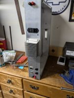
Here's an update on my progress on this amp. Chassis work had begun.
I've constructed a solid state preamp/crossover for the input of this amp. I just wanted to have balanced inputs and to be able to biamp with a subwoofer. The crossover has a bypass switch in case I don't want to use it. I also need a bit of gain up front for some sources.
I've constructed a solid state preamp/crossover for the input of this amp. I just wanted to have balanced inputs and to be able to biamp with a subwoofer. The crossover has a bypass switch in case I don't want to use it. I also need a bit of gain up front for some sources.
Attachments
Looking good!
Beware of vibrating power transformers, I had to rebuild the PSU for my 808 amp completely because of that. All those flat .040" alu sheets (with the same surface area as four 18" drivers...) sang along with the transformers even with rubber dampers everywhere, in the end I moved everything over to a box made of welded .05" steel that I stole from a scrapped CNC lathe that was rusting away behind my old workplace... 😎
Beware of vibrating power transformers, I had to rebuild the PSU for my 808 amp completely because of that. All those flat .040" alu sheets (with the same surface area as four 18" drivers...) sang along with the transformers even with rubber dampers everywhere, in the end I moved everything over to a box made of welded .05" steel that I stole from a scrapped CNC lathe that was rusting away behind my old workplace... 😎
What type number is that little blue tube? I have one but the marking is gone.I guess the only way to know for sure is to try it. Replacing the input tubes and adding feedback resistors should be easy enough, and even my old `scope shoould be able to tell if anything dramatic happens. I once got severe oscillations in a test circuit with an 808 and some high gm driver tube, it was easily spotted as the 808 plate suddenly went from dull red to bright orange and everything started to make crackling sounds... 😀
Sort of, yes. The easiest way to make a driver stage with a delayed soft start was to use a choke loaded indirectly heated cathode follower.
As I'm using SS diodes in the power supply (+500V and +250V from a 180-0-180VAC transformer) I had to take some measures to make life as easy as possible for the output tubes during startup. The best I could come up with without timer circuits etc. was a choke loaded cathode follower where the cold end of the choke connects to a negative low voltage rail and the CF tube has a thermistor in series with its heater to add some extra delay. This way, the output tubes are biased into complete cutoff until their filaments have reached their full emission capacity.
Things get a bit more complicated as I intend to build this amp to fit three different output tubes with different bias requirements (+23V for TZ20, +12V for T20 and around 0V for 8025A), the solution was to use a few spare heater windings to make a "ladder" of negative voltages available. This way the voltage drop through the choke and thus the idle current through the CF can be kept fairly constant.
A conceptual drawing of the driver/output stage:
View attachment 1341531
As mentioned, I'm already quite impressed by the sound from the prototype. A bit "woolly" in the bass but slightly more "civilized" than my 808 SET.
I could build it as is, with a different input stage and a little bit of extra feedback, or I could take a completely different route: CCS loaded mosfet followers as grid drivers and 24A globe bottles as input tubes, operating as tetrodes with feedback from output anodes to input cathodes.
I have a few globe 24As (even a few blue Arcturus ones) that make a great visual match to the output tubes but their technical merits are questionable and getting rid of the IDH CF driver would complicate things a bit regarding the startup sequence.
View attachment 1341532
Arcturus 124What type number is that little blue tube? I have one but the marking is gone.
I believe the old #24 exists in a myriad of versions: 24, 24A, 124, 224, 324, UY224 and so on. If the numbers are completely rubbed off it could also be a 35 or a 51, as far as I can tell they look the same.
Anyhow, after thoughtful consideration I've (almost) decided against using vintage #24 tubes in my amp in favor of "modern" octal tubes. The old American globe tubes are almost impossible to find here in EU and shipping them from across the pond is ridiculously expensive, especially considering almost all of them are well used and mostly sold as singles. It was bad enough to go through that routine to stock up on the output tubes who are also virtually non-existent in Europe.
I'll still keep an eye open for globe 24s, especially the blue ones from Arcturus, but I'll put them in a line stage or something instead.
If you are open to using a more modern tube, the 6BN11 I used looks pretty neat with the glowing wire that connects the two cathodes and the open plate structure, and you get two pentodes in one tube. They are dirt cheap, too. I bought dozens because they were so cheap. But they are a compactron tube.
A cool looking tube for sure, but a bit too modern-looking for this projekt. Unless I change my mind again I'll cut holes for two octal sockets per channel, that should leave me with plenty of options for both input and CF tubes. Using noval sockets for the driver tubes would allow me to use tubes with some serious gm for the CFs but the 25E5 (~6CM5, EL36, PL36) gets the job done and can be replaced with the pin compatible E130L (27mA/V) later on.6BN11
As input tubes I can think of several single triodes or pentodes that chould cut it, depending on how the plate to cathode feedback experiment goes. 6J7 or 6SJ7 should do nice as pentode input stages, and I have some nice CV1135s (~1/2 6SN7 with dual top caps) if I want to stick with medium mu triodes.
The picture shows a T20 next to a PL36 and a CV1135. A sweep tube with similar specs to the PL36 but in a fatter bottle would be nice, there is probably some American tube that I don't know about that would fit the bill. 6DQ6 somes close but has lower gm according to the datasheet.


My experiments with output plate to input cathode feedback in the T20 amp didn't turn out too well: After fiddling with the resistor values around the 6SJ7 I managed to get a but over 2dBs of feedback. It currently has 66k plate resistors, 470R cathode resistors, 200k feedback resistors and 95V on the screen grids.
I guess I should have picked an input tube with a bit more gm.
I guess I should have picked an input tube with a bit more gm.
- Home
- Amplifiers
- Tubes / Valves
- Corona: An Ultra-Low Distortion A2 DHT SE Amp Prototype