Hello ra7,
Your arrays are different than mine mainly due its corner loading design and hence minimum delayed reflection from the front wall. I have found that by varying the distance of my arrays from the front wall the soundstage depth slightly varies ( i.e. depth somewhat increases with increasing distance). On the other hand, placing the arrays nearer the front wall improves the bass profile. I'd have loved to corner mount my speakers to find out how much of soundstage depth I am compromising for better bass. Sadly, I can get them too close to the corner due to the fixed speaker stands.
So, just curious enough to ask you, how would you describe the soundstage depth of your speakers? satisfied enough?
Also, please mention the width of your front wall. I assume the side panels of your triangular cabinet are of same width. This would help me knowing the fixed toe-in of your arrays.
You mentioned a conjugate network to flatten the impedance.
As long as we're trying to be clear about everything, I tried a conjugate network on the entire impedance plot. BYRTT helped me to get going and learn to use bwaslo's XSIM to get the best values for my impedance plot.

The result can be seen here:

Impedance plot of speaker vs impedance plot with speaker and conjugate network
I did a couple of experiments with this, even hooked up some series resistor(s). After some tests with the correction in and out I removed the correction for the rising impedance at higher frequencies.
That made the impedance of the speaker + conjugate look like this:

This is what I still use today. Though there are minute changes in behaviour around the impedance peak in a comparison it didn't quite explain a perceived difference I was getting. So this remains a subjective choice. No scientific explanation from my side, just a preference.
So the parts that remain are the branch R1, L1, C1&2, R2.
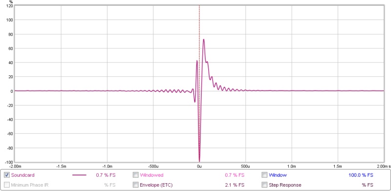
On the impulse part, here's a measured impulse:

In all honesty, one of the cleanest I ever measured (FIR corrected of coarse), but remember we're mostly looking at high frequency material here. But DRC-FIR definitely helps clean up the impulse and STEP performance. (target was set to flat)
Last edited:
Attached is a new set of measurements that I made just now (extract the zip. The REW format was 13 MB after being zipped, so, the measurements are exported as text files). The first couple of measurements are those with loopback and calibration of the DAC/ADC loop. Below, I will explain each measurement in order:
1. Soundcard Loopback. REW Settings: JAVA drivers. EMU USB card selected for both input and output. In Windows, EMU is the default sound card. In JRiver, WASAPI loopback. Output of DAC from JRiver physically connected to mic input of EMU card.
2. Soundcard Loopback. REW Settings: ASIO drivers. EMU USB card selected for both input and output. Output from EMU is physically connected to input of Behringer I/O USB DAC. In JRiver, use ASIO loopback and "listen" to input of Behringer. Output of DAC from JRiver physically connected to mic input of EMU card.
Clearly, the second option is much better. I used this to calibrate the loop in REW. Then did the following measurements.
3. Line array only (no sub) left uncorrected.
4. Line array only (no sub) right uncorrected.
5. Line array only (no sub) left corrected.
6. Line array only (no sub) right corrected.
These measurements look much better. The impulse is clean for both channels.
One of the reasons I highly recommend checking loopback results to everyone.
That second pulse looks clean enough. Is the accompanying FR nice and flat?
Got to be judging by the impulse.
I looked at the txt files. Too bad it does not contain any real info. We cannot "travel trough time" so to speak 😀. No real info except the static plot.
Pretty steep slope on the low end though...
Attached is a new set of measurements that I made just now (extract the zip. The REW format was 13 MB after being zipped, so, the measurements are exported as text files). The first couple of measurements are those with loopback and calibration of the DAC/ADC loop. Below, I will explain each measurement in order:
1. Soundcard Loopback. REW Settings: JAVA drivers. EMU USB card selected for both input and output. In Windows, EMU is the default sound card. In JRiver, WASAPI loopback. Output of DAC from JRiver physically connected to mic input of EMU card.
Like I've been saying, that is not the correct way to use the Live:Loopback feature in MC. If the Loopback feature is active when you have everything setup like this I wonder if you are getting a second pulse looped back though like I said before. I'm glad your method is working tho.
Good catch, indeed this isn't the way to hook up the loop trough JRiver.
Set the windows default device to an unused soundcard. NOT the soundcard used in JRiver. Now set REW to use the default device, meaning it will use that unused soundcard.
In JRiver use the "Open Live" -> Wasapi Loopback to route the signal from the unused soundcard trough JRiver and output to the driver chosen within JRiver.
I'm surprised it works at all...
From JRiver 20 and up you can do much of the same using the JRiver WDM driver (if it works for you) and you wouldn't need the loopback feature. Even though I'm still on JRiver 19, I do use the WDM driver from version 20. I upgraded to JRiver 21, meaning I paid for it but have not installed/used it yet. It let me use JRiver 20 but somehow it was not sounding exactly the same as version 19 at the time. So I continued to use version 19. I bet I could find the reason for the difference I experienced with a cable loopback of the signal, routing the DAC back into the mic input. Haven't bothered to do that yet.
Had also been exercising with the setups as natehansen66 and wesayso talk about, and what helped for my setup to give best IR precision from sweep to sweep and most staple low distortion from sweep to sweep was manual setting all involved hardware/virtual sound devices to same samplerate in Windows sound controlpanel for I/O devices. Know Windows can do SRC that works, but if at first before a measurement i set up involved hardware and JRiver virtual device to lock to same 48kHz and ensure REW Java is also set to 48kHz plus ensure JRivers SRC container plugin is not converting anything setup gets staple. Also in miniDSP USB controlpanel from THESYCON can imagine the USB Streaming mode setting could be worth try some tweaking.
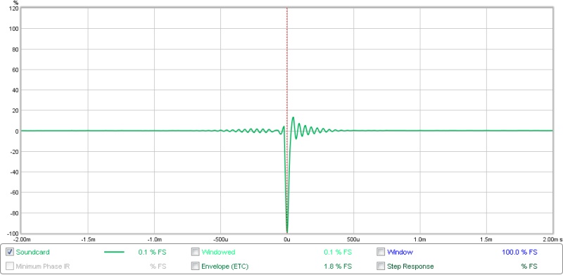
I think that's a good call, to illustrate a loopback from my system (using jriver wdm) if there is sample rate disagreement. Completely clean impulse vs the ripple from the resamplerHad also been exercising with the setups as natehansen66 and wesayso talk about, and what helped for my setup to give best IR precision from sweep to sweep and most staple low distortion from sweep to sweep was manual setting all involved hardware/virtual sound devices to same samplerate in Windows sound controlpanel for I/O devices. Know Windows can do SRC that works, but if at first before a measurement i set up involved hardware and JRiver virtual device to lock to same 48kHz and ensure REW Java is also set to 48kHz plus ensure JRivers SRC container plugin is not converting anything setup gets staple. Also in miniDSP USB controlpanel from THESYCON can imagine the USB Streaming mode setting could be worth try some tweaking.

Using ASIO should be the simple way to avoid this though (as then the windows sample rate conversion is not in play). Mind you yours looks sharp enough but is surrounded by some other fuzz/noise, have you looped back the device alone to isolate the device vs jriver?
Last edited:
I think that's a good call, to illustrate a loopback from my system (using jriver wdm) if there is sample rate disagreement. Completely clean impulse vs the ripple from the resampler
.....
Thanks that IR plot.
.....Using ASIO should be the simple way to avoid this though (as then the windows sample rate conversion is not in play).....
Also as with ASIO WASAPI is much more simple and audiophile with its exclusive hardware access and seems not bad, but for the measurement situation the two programs to at same time have exclusive access ASIO/WASAPI is problem.
Own experience so far is if a interface has ASIO driver that work okay it also performs better in loopback distortion measurements than WASAPI and Windows sound system.
yeah it's handy to have a multiclient capable asio driver or you can try the steinberg multiclient proxy (https://www.steinberg.net/forums/viewtopic.php?f=34&t=48). IME these things (especially jriver) are also be quite sensitive to the various buffer sizes that you can set & some are also sensitive to the particular interface (port) you use.Also as with ASIO WASAPI is much more simple and audiophile with its exclusive hardware access and seems not bad, but for the measurement situation the two programs to at same time have exclusive access ASIO/WASAPI is problem.
Own experience so far is if a interface has ASIO driver that work okay it also performs better in loopback distortion measurements than WASAPI and Windows sound system.
Looks like you've got it going.
FWIW, yes, I do calibrate the sound card because it's so easy to do so. Not really needed for speaker work, as the sound card is so much flatter and more extended than any speaker or mic I'll ever own.
So. You have 24 drivers per side? All butted up tight against each other on the flat flange? That should come out to 7ft long. If the cones are so close to each other, I wonder what effect that has on comb filtering. At longer wavelengths it shouldn't be bad, as the cones are almost touching each other.

Yeah, the soundcard is flatter, but I don't think it is a trivial matter to get the loopback through JRiver to work flawlessly.
Yes, 24 drivers per side, 7 ft long. Where the cones are omnidirectional, it acts like a single driver and a cylindrical wavefront. When they become directional, it will result in lobing, just like a woofer and dome near the crossover. But with so many drivers combining and cancelling, I think you should still get some gain. If you sit far away from the array, and are not doing situps while listening, the comb filtering should not be audible. The comb width is very fine because there are so many drivers and their floor/ceiling reflections and the ear cannot distinguish the finely spread high Q comb (Toole says as much in his book). There are many folks here who have a similar long array and only one of them so far has complained about comb filtering, though in my opinion the complaint is because he or she failed to do proper EQ on the arrays.
Yes, 24 drivers per side, 7 ft long. Where the cones are omnidirectional, it acts like a single driver and a cylindrical wavefront. When they become directional, it will result in lobing, just like a woofer and dome near the crossover. But with so many drivers combining and cancelling, I think you should still get some gain. If you sit far away from the array, and are not doing situps while listening, the comb filtering should not be audible. The comb width is very fine because there are so many drivers and their floor/ceiling reflections and the ear cannot distinguish the finely spread high Q comb (Toole says as much in his book). There are many folks here who have a similar long array and only one of them so far has complained about comb filtering, though in my opinion the complaint is because he or she failed to do proper EQ on the arrays.
I'd like to ask a clarifying question if I may. Comb filtering and Combing are referred to often in Line Array discussions. By Comb Filtering do we mean the undulation is gain that occurs along the vertical as drivers get directive or do we mean the classic frequency response nulls that occur due to superposition of initial and late arriving signals (in this case due to signals from far drivers). The latter would be more like what Toole refers to I think.
Good question. In the context of the discussion in this thread, I think we mean the second thing you describe. The response at a given point looks like a fine toothed comb. I am contending that this is not audible, given the relatively wide perceived bandwidth of the ear and the fineness of the comb.
I am not sure at what frequency the directivity of the array will change as the drivers become more directive.
I am not sure at what frequency the directivity of the array will change as the drivers become more directive.
There are many folks here who have a similar long array and only one of them so far has complained about comb filtering, though in my opinion the complaint is because he or she failed to do proper EQ on the arrays.
I believe we can't or not supposed to EQ comb filtering. Comb filtering is a dependent on listening distance. If you compare two unsmoothed FR graphs say one at 3m and another at 3.5m, you will notice the comb filtering pattern has shifted to different frequencies.
The full range driver even when working alone has a lot of undulations. So naturally the array will too; add baffle diffraction. One may confuse these relatively low Q undulations with comb filtering which are rather very very high Q dips.
Such high Q dips of comb filtering are not audible to our ear, at least mine. Its the inherent undulations of the full range driver that one may complain to be hearing as comb filtering. These undulations can be EQed if required which does not change with listening distance. And for this purpose a graphic EQ is pretty much useless and will mostly always make things worse.
Hello ra7,
Your arrays are different than mine mainly due its corner loading design and hence minimum delayed reflection from the front wall. I have found that by varying the distance of my arrays from the front wall the soundstage depth slightly varies ( i.e. depth somewhat increases with increasing distance). On the other hand, placing the arrays nearer the front wall improves the bass profile. I'd have loved to corner mount my speakers to find out how much of soundstage depth I am compromising for better bass. Sadly, I can get them too close to the corner due to the fixed speaker stands.
So, just curious enough to ask you, how would you describe the soundstage depth of your speakers? satisfied enough?
Also, please mention the width of your front wall. I assume the side panels of your triangular cabinet are of same width. This would help me knowing the fixed toe-in of your arrays.
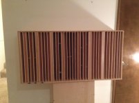
Yes, the front wall reflection kind of ruins the depth perception. You could try putting some absorbers, or better yet diffusers to improve the depth. See attached pic of a diffuser I built, which is currently sitting right behind the listening position.
The best depth perception I've heard is on Pano's all horn system. The arrays come very close to that. Depth and precision of instrument positions is very good, especially on orchestral recordings. Church choir recordings sound like you are in a church with the organ far away.
Width of wall is 13 ft. Yes, the side walls of the cabinet are of the same width. Basically, it fits right into the corner. So, they are firing 45 degrees inwards. I just measured my listening distance and it is 16 feet from each corner. I'm still experimenting with the setup, including the absorption panels.
Attachments
As long as we're trying to be clear about everything, I tried a conjugate network on the entire impedance plot. BYRTT helped me to get going and learn to use bwaslo's XSIM to get the best values for my impedance plot.
The result can be seen here:
Impedance plot of speaker vs impedance plot with speaker and conjugate network
I did a couple of experiments with this, even hooked up some series resistor(s). After some tests with the correction in and out I removed the correction for the rising impedance at higher frequencies.
That made the impedance of the speaker + conjugate look like this:
This is what I still use today. Though there are minute changes in behaviour around the impedance peak in a comparison it didn't quite explain a perceived difference I was getting. So this remains a subjective choice. No scientific explanation from my side, just a preference.
I might try it. But I remember reading one of Speaker Dave's post saying it doesn't do much. If you are doing a passive crossover then you can build in the network. But with all active EQ and crossover (to the sub), there may be no need to do it.
Like I've been saying, that is not the correct way to use the Live:Loopback feature in MC. If the Loopback feature is active when you have everything setup like this I wonder if you are getting a second pulse looped back though like I said before. I'm glad your method is working tho.
Good catch, indeed this isn't the way to hook up the loop trough JRiver.
Set the windows default device to an unused soundcard. NOT the soundcard used in JRiver. Now set REW to use the default device, meaning it will use that unused soundcard.
In JRiver use the "Open Live" -> Wasapi Loopback to route the signal from the unused soundcard trough JRiver and output to the driver chosen within JRiver.
I'm surprised it works at all...
From JRiver 20 and up you can do much of the same using the JRiver WDM driver (if it works for you) and you wouldn't need the loopback feature. Even though I'm still on JRiver 19, I do use the WDM driver from version 20. I upgraded to JRiver 21, meaning I paid for it but have not installed/used it yet. It let me use JRiver 20 but somehow it was not sounding exactly the same as version 19 at the time. So I continued to use version 19. I bet I could find the reason for the difference I experienced with a cable loopback of the signal, routing the DAC back into the mic input. Haven't bothered to do that yet.
I think there is some miscommunication here. There is no scope for feedback in my loop. I was using the EMU card in REW and also setting the EMU card as the default in Windows (what you guys are calling the "unused" card). That's how the loopback in JRiver picks up the signal. The final playback is on an entirely different card. So, there is no chance of a second pulse.
BTW, the graphs that I showed were the best of the lot. There are many different ways to do loopback in JRiver, and using some of the other ways gives an even worse impulse response. For example, by selecting the JRiver driver as output in REW.
Anyway, with everything using ASIO, it works and I get a reasonably clean impulse. Also, like Pano says, it's a good idea to put the DAC/ADC calibration into the measurement chain, so that its effect can be accounted for.
Last edited:
I think that's a good call, to illustrate a loopback from my system (using jriver wdm) if there is sample rate disagreement. Completely clean impulse vs the ripple from the resampler
View attachment 521809
Using ASIO should be the simple way to avoid this though (as then the windows sample rate conversion is not in play). Mind you yours looks sharp enough but is surrounded by some other fuzz/noise, have you looped back the device alone to isolate the device vs jriver?
Thank you BRYTT and 3ll3d00d (wow, that's a mouthful!) for your comments. Sample rate switching could have something to do with it. The attached impulse at 44.1 kHz is pretty impressive. Can you describe more the settings in REW, JRiver and Windows to get that impulse?
As I described earlier, the best setup I was seeing was piping the output of the EMU physically into an intermediate card's input (Behringer USB I/O device) and then listening to that device using ASIO loopback in JRiver. I'd have to isolate the loopback through the EMU and then through the Behringer, but not sure what I'd do with that.
I believe we can't or not supposed to EQ comb filtering. Comb filtering is a dependent on listening distance. If you compare two unsmoothed FR graphs say one at 3m and another at 3.5m, you will notice the comb filtering pattern has shifted to different frequencies.
The full range driver even when working alone has a lot of undulations. So naturally the array will too; add baffle diffraction. One may confuse these relatively low Q undulations with comb filtering which are rather very very high Q dips.
Such high Q dips of comb filtering are not audible to our ear, at least mine. Its the inherent undulations of the full range driver that one may complain to be hearing as comb filtering. These undulations can be EQed if required which does not change with listening distance. And for this purpose a graphic EQ is pretty much useless and will mostly always make things worse.
You are correct, of course. But what I was trying to say is that sometimes improper EQ can lead to less than good sound and the blame always (though incorrectly) falls at the feet of comb filtering. I wasn't trying to say that we should fix the comb filtering.
Ra7 and I were taking about this very subject last night. I was curious how much depth the line arrays are capable of, seeing that they are in the corners and do from floor to celling.Yes, the front wall reflection kind of ruins the depth perception. You could try putting some absorbers, or better yet diffusers to improve the depth.
For me, front wall reflections really kill the illusion of depth. But most of us are stuck with it.
At the moment I am lucky to have 35' (about 10m) behind my speakers with highly decorrelated reflections. The floor to ceiling array tight in the corner could be a clever way to extend the depth illusion, without having actual depth behind the speakers.
I believe we can't or not supposed to EQ comb filtering. Comb filtering is a dependent on listening distance. If you compare two unsmoothed FR graphs say one at 3m and another at 3.5m, you will notice the comb filtering pattern has shifted to different frequencies.
The full range driver even when working alone has a lot of undulations. So naturally the array will too; add baffle diffraction. One may confuse these relatively low Q undulations with comb filtering which are rather very very high Q dips.
Such high Q dips of comb filtering are not audible to our ear, at least mine. Its the inherent undulations of the full range driver that one may complain to be hearing as comb filtering. These undulations can be EQed if required which does not change with listening distance. And for this purpose a graphic EQ is pretty much useless and will mostly always make things worse.
This is exactly why I suggest EQ-ing the top end (and bottom for that matter) with a relative short window. That will average the dips and peaks and that average gets corrected, not individual peaks and dips. The comb pattern will change with every move. The other advantage is not trying to correct the room effects of these higher frequency, happening later in time. The diffraction anomalies are probably within the window of correction as they happen very early in time.
- Home
- Loudspeakers
- Multi-Way
- Corner Floor-to-Ceiling Line Array Using Vifa TC9