My understanding is different. A line array produces a cylindrical wavefront for frequencies proportional to its line length.
That's definitely ideal, but from what I've read in a couple of places, hard to do without vertically large transducers. I mean, yes, I get the line array seduction of having a perfectly cylindrical wave front. And until recently I didn't realize the complexity involved.
Longer the array, lower in frequency extends the cylindrical nature of the wavefront. What that means is that when measured at any point along the vertical dimension on the cylinder, the sound is the same.
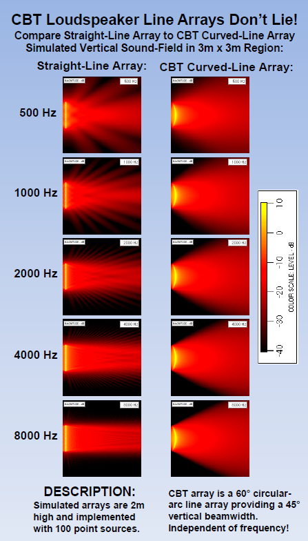
I think the problem is whether the transducers act as point sources or not. Here is a great slide from Don Keele's site. Notice how the individual point sources don't "gel" together until 8 kHz. I think you achieved better by using relatively large drivers to cover the full range. Had you used a line of tweeters, you would have ended up looking more like the top left slide.
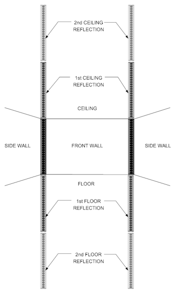
What Keele failed to take into account in those pictures is the floor and ceiling reflections of a floor to ceiling array. Somehow he remembered to apply that mirror image for the CBT array though 🙄.
You see how his CBT array represents a full curve, while his actual speakers are only half of that? Then shouldn't he have added the same benefits to the full length array by adding the floor and ceiling reflections to that one too?
I think of that example as a misrepresentation of the floor to ceiling line array.

What Keele failed to take into account in those pictures is the floor and ceiling reflections of a floor to ceiling array. Somehow he remembered to apply that mirror image for the CBT array though 🙄.
You see how his CBT array represents a full curve, while his actual speakers are only half of that? Then shouldn't he have added the same benefits to the full length array by adding the floor and ceiling reflections to that one too?
I think of that example as a misrepresentation of the floor to ceiling line array.
Um, I think you took this in a very different direction. The issue with line arrays I was trying to make, and that slide shows, was not about reflections, but rather the myth that "all line arrays produce cylindrical wavefronts."
The key word here being "all." Not all do, and if they do they may not do so at all frequencies.
Another implication of those slides is that it may be possible to get much of the benefits of a line array without going floor to ceiling IF your driver sizes are such that the individual wavefronts are planar and not point-sources.
Best,
Erik
Best,
Erik
And I think you failed to see my point. Missing it entirely in fact.
Never mind..
I am terribly sorry, but you are right, I did miss your point. 🙂
Were you replying to my statement or making a new one about Keele's convenient choice of measurements? Sorry I was confused in how it fit in the thread. I'll have to do more reading to understand. I haven't been following his CBT propaganda that much. I did see some cheesy demo where he put a mirror on the floor, claiming it was proof of perfect reflections or something. Was your point along those lines?
Best,
Erik
What Keele showed in his example is use the floor mirror in the CBT simulation.
If you want to compare that to a floor to ceiling array, you should include those too when simulating that type of array.
If your interest would be to create a shorter array I'd recommend to use shading techniques. But I don't recommend the use of shading with a floor to ceiling array.
Not trying to be blunt here. Do read the Speaker Dave papers and posts on this subject.
They do help in understanding the difference here.
The key part of the floor to ceiling requirement is to make it behave like a much longer array than it really is. To preserve that cylindrical wave shape over a wider frequency range. Though I've done my share of measurements I haven't made an effort to prove this as my room isn't big enough to do the measurements it would take to show it.
Basically I'm saying that a floor to ceiling array will be very different from a shorter one.
I'm sure the choice from ra7 is a deliberate one to go floor to ceiling. It was for me.
Are you being serious here? 😀
Well at least partly? With the right processing something like this would be mind-blowing!
I'd have to agree... need to play Jennifer again but do not have the house to myself this week. I haven't had the depth suggested in the lower chart, but have way more focus than the upper one suggests.
I agree to have heard more separation on other tracks. But I find these charts fun to compare to. I used a couple of tracks as reference all trough my journey and that Jennifer Warnes track did not make it into that selection.
No, I was kidding, though I wish I wasn't 🙂. If I had more money and time, I would do it. But you have to wonder if it is a waste of resources (let Pano have a few TC9s for his troglodytes 😀). I haven't quite jumped on the HT bandwagon yet. Too much complexity and not enough pleasure to be gained, IMO.
I think there is something missing here. The floor-to-ceiling line array using 3.5" TC9s stacked really close together does resemble a "vertically large transducer."That's definitely ideal, but from what I've read in a couple of places, hard to do without vertically large transducers. I mean, yes, I get the line array seduction of having a perfectly cylindrical wave front. And until recently I didn't realize the complexity involved.
I think the problem is whether the transducers act as point sources or not. Here is a great slide from Don Keele's site. Notice how the individual point sources don't "gel" together until 8 kHz. I think you achieved better by using relatively large drivers to cover the full range. Had you used a line of tweeters, you would have ended up looking more like the top left slide.
That slide is completely misleading. He is comparing a short line array to his curved short array. If you appropriately delay the elements of the straight array, it should perform exactly the same as the curved array. The curvature does not do anything other than adding a delay. Read the Speaker Dave paper linked earlier.
The floor-to-ceiling array starts "gelling" from 160 Hz. It starts to "un-gel" at about 4 kHz when the 3.5" drivers start beaming. If I had used smaller drivers it would be more ideal because the beaming would start at a higher frequency. The difference between what is being said here and Keele's sim is in the length of the array. Shorter arrays need more processing (delay, progressive roll off of outer elements, and shading) to come close to the performance of a floor-to-ceiling array.
Read Speaker Dave's paper.
Wesayso, you and I both use JRiver. Can you describe how you measure with the correction in place? What is your measurement setup?
And finally, how do you EQ? You mentioned a conjugate network to flatten the impedance. Is there any other correction before measuring for the FIR correction? Your graphs look really really smooth and flat. Mine don't. What is the difference?
And finally, how do you EQ? You mentioned a conjugate network to flatten the impedance. Is there any other correction before measuring for the FIR correction? Your graphs look really really smooth and flat. Mine don't. What is the difference?
What Keele failed to take into account in those pictures is the floor and ceiling reflections of a floor to ceiling array.
Even given that, above 1 kHz a full height vertical array still looks like a better solution to me. Less HF spray from the ceiling and floor.
This is how Dennis Murphy explains how reflections work for floor-to-ceiling array. But still, I don't believe in sharp impulse. A good one ok, but not sharp.
https://trueaudio.com/array/MCLA_design.htm
https://trueaudio.com/array/MCLA_design.htm
Last edited:
I'm not wesayo obviously but I am a JRiver/REW user. He's using a 4 cycle freq dependent window in REW and, iirc, psychoacoustic smoothing. Both are available in the latest release. I'd venture a guess and say the fdw is similar to the windowing scheme in DRC....at least it's closer than the fixed window and smoothing you're doing now. IMO the 4 cycle window is too coarse below 500hz or so and I use more like 10-15.Wesayso, you and I both use JRiver. Can you describe how you measure with the correction in place? What is your measurement setup?
And finally, how do you EQ? You mentioned a conjugate network to flatten the impedance. Is there any other correction before measuring for the FIR correction? Your graphs look really really smooth and flat. Mine don't. What is the difference?
I remember talking to you about your measurement setup before (in one of your threads?). Can you remind me what it is? Iirc it was "convoluted" as you say.
Very cool project btw. Sorry if I missed it, but did you say why you gave up on the expanding array?
This is how Dennis Murphy explains how reflections work for floor-to-ceiling array. But still, I don't believe in sharp impulse. A good one ok, but not sharp.
https://trueaudio.com/array/MCLA_design.htm
I don't know about that second reflection. But the first one is a well known effect of a floor to ceiling array. The sharp impulse is not a thing of belief, it's real.
To measure thru JRiver, use the ASIO loopback. File/Live
It won't let me use the same input and output card. Have to use two.
It won't let me use the same input and output card. Have to use two.
ra7 - I measure in REW with the java drivers. I set the JRiver WDM driver as Windows default driver.
In JRiver I have the driver set to the Asio driver for the Xonar Essense ST. As mentioned I do use a gentle pré EQ with JRiver's PEQ settings. The Asus feeds my Musical Fidelity M1 DAC that feeds the amp. The recording is a (professionally) calibrated Behringer mic -> MPA 102 line stage -> Asus Mic in.
Nate already said it, I use REW's frequency dependant cycle gating. I always mention it below the graphs not to confuse anyone. I do the gating as I want to see what signal hits the listener first. As you know by now, I believe that first wave front to be the most important. As long as the response after that first wave front does not get messed up too much by the room. In other words, get it down as much as you can in SPL level.

REW gated 4 cycle frequency dependant window of a L+R measurement.
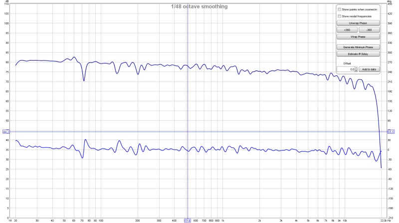
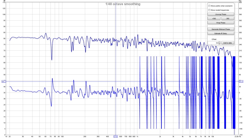
Same measurement with the window set to 15 cycles FDW. But think about what time frame a 15 cycle window is at say 100 Hz! We are talking about 150 ms with 15 cycles. The precedence effect is said to hold up to about ~30 ms.
So I do think the 4 cycle window has some meaning as to what we perceive at that frequency. (* More below)
1/48 octave smoothed standard window in REW.
*: If we check the Wavelet plot (set to 28 ms):

You can see the first wave front to be contiguous. So my perception is set on that wave hitting my ears. Slight tonal changes may happen due to later room behaviour, but it will be down by 20 dB already (if it were a short blast).
It is highly debatable how we actually perceive sound. I believe the first wave front to be the most important (due to that precedence effect). So I did what I could to let it arrive as smooth as possible and in time! 😉
My room is a living room. Much of the signal gets messed up after that first wave. But due to the precedence effect I can add my ambient speakers 20 ms behind the mains without actually hearing them as separate speakers at any time. Yet they do change perception of the imaging. As reflections will change the perception within that same time frame. My biggest hurdles are a big dip in the left channel at 72 Hz. And two smaller dips in the right channel at 135 and 203 Hz. Other than that the processing and damping panels clean it up nicely. Phase is a mess however after the first wave front due to multiple later reflections. But by then the perception has already taken place i.m.h.o.
**Already had most of this typed in and lost it. Hope it still makes sense 😉**
In JRiver I have the driver set to the Asio driver for the Xonar Essense ST. As mentioned I do use a gentle pré EQ with JRiver's PEQ settings. The Asus feeds my Musical Fidelity M1 DAC that feeds the amp. The recording is a (professionally) calibrated Behringer mic -> MPA 102 line stage -> Asus Mic in.
Nate already said it, I use REW's frequency dependant cycle gating. I always mention it below the graphs not to confuse anyone. I do the gating as I want to see what signal hits the listener first. As you know by now, I believe that first wave front to be the most important. As long as the response after that first wave front does not get messed up too much by the room. In other words, get it down as much as you can in SPL level.
REW gated 4 cycle frequency dependant window of a L+R measurement.
Same measurement with the window set to 15 cycles FDW. But think about what time frame a 15 cycle window is at say 100 Hz! We are talking about 150 ms with 15 cycles. The precedence effect is said to hold up to about ~30 ms.
So I do think the 4 cycle window has some meaning as to what we perceive at that frequency. (* More below)
1/48 octave smoothed standard window in REW.
*: If we check the Wavelet plot (set to 28 ms):
You can see the first wave front to be contiguous. So my perception is set on that wave hitting my ears. Slight tonal changes may happen due to later room behaviour, but it will be down by 20 dB already (if it were a short blast).
It is highly debatable how we actually perceive sound. I believe the first wave front to be the most important (due to that precedence effect). So I did what I could to let it arrive as smooth as possible and in time! 😉
My room is a living room. Much of the signal gets messed up after that first wave. But due to the precedence effect I can add my ambient speakers 20 ms behind the mains without actually hearing them as separate speakers at any time. Yet they do change perception of the imaging. As reflections will change the perception within that same time frame. My biggest hurdles are a big dip in the left channel at 72 Hz. And two smaller dips in the right channel at 135 and 203 Hz. Other than that the processing and damping panels clean it up nicely. Phase is a mess however after the first wave front due to multiple later reflections. But by then the perception has already taken place i.m.h.o.
**Already had most of this typed in and lost it. Hope it still makes sense 😉**
Last edited:
I think there is something missing here. The floor-to-ceiling line array using 3.5" TC9s stacked really close together does resemble a "vertically large transducer."
No, it doesn't. The dispersion and directivity would be completely different if such a driver existed. The closest example of your comparison would be of a limited response range and the B&G planars........whose dispersion and directivity are NOTHING like an equally long line of TC9's.
Let's dispel myths, not create new ones. You've already acknowledged beaming so that has to used in context, not convenience for the sake of argument.😀
Pano, I've used live before, both Wasapi (JRiver driver) and ASIO loopback. Can you be more specific about the routing of input and output, and soundcard/driver selection in REW?
Wesayso, my setup is similar to yours. I use a custom multichannel DAC built using miniDSP products. It has 8 channels on i2s, IIRC. I have tried a connection similar to yours, i.e., select JAVA drivers in REW, output is JRiver, and input (mic) in EMU0204. Or, I have also done JAVA drivers, I/O set to EMU, then set EMU as the default in Windows, and use Wasapi Loopback in JRiver to pick up the sound and play it through the speakers. In both these setups, I get a funky impulse (you've seen it posted in your thread).
Now, here's my convoluted setup that gives the cleanest impulse:
1. Select ASIO drivers in REW. Choose I/O as EMU.
2. Take analog out from EMU and put it as input to a Behringer USB DAC.
3. Choose ASIO loopback in JRiver and get input from the Behringer (ASIO) to play it through the JRiver engine.
Question to both you and Pano: Do you guys calibrate the DAC/ADC chain? That is, loop the output to the input and measure. Holm has this feature, I'll have to check REW. But it may be one way to take the impact of the loopback out of the equation.
Now coming to the key issue: I think the reason your measurement looks so clean is the 4-cycle filter in REW. Where is this selection? I see the ERB, psychoacoustic and variable smoothing options, but haven't seen an option to set the variable window.
I presume you are also using the 4 cycle filter in DRC. When you feed the measurement to DRC, that is just the raw measurement correct? No pre-processing in REW?
I did not calibrate my DAC. I did do a loopback of the chain and optimised (Asio) buffers for the best result. Loopback was a physical cable from DAC to Mic in.
Impulse and STEP response
More closely zoomed in examples in my thread. In DRC I do not use a 4 cycle window. It's actually something like 6 cycles at 20 Hz, down to just over 4 cycles in mid frequencies and growing to 11 cycles at 20000 Hz.
And a totally different Excess phase window over only part of the frequency range from 20 Hz up to 500 Hz. Not as originally intended by Denis Sbragion 🙂.
The cycle dependant window in REW can be found here:

The raw impulse as measured in REW is used in DRC-FIR. I export it in REW at Mono, 32 bit and I use Normalise. Nothing else.
From there I've created batch files to do the rest of the work for me. Except changing the .wav export to .PCM format in CoolAudio.
This gives me a visual queue to see if everything is OK.
I generate both correction filters as well as simulated output in DRC. To be able to see it directly and compare to real measurements.
Impulse and STEP response
More closely zoomed in examples in my thread. In DRC I do not use a 4 cycle window. It's actually something like 6 cycles at 20 Hz, down to just over 4 cycles in mid frequencies and growing to 11 cycles at 20000 Hz.
Code:
Minimum phase component single side sliding lowpass prefiltering.
Input signal prewindowing.
R - Initial lowpass convolution...
R - Band:   0,    20.0 Hz, width:  13230, FIR, convolution...
R - Band:   1,    25.2 Hz, width:   9821, FIR, convolution...
R - Band:   2,    31.7 Hz, width:   7416, FIR, convolution...
R - Band:   3,    40.0 Hz, width:   5668, FIR, convolution...
R - Band:   4,    50.4 Hz, width:   4372, FIR, convolution...
R - Band:   5,    63.5 Hz, width:   3395, FIR, convolution...
R - Band:   6,    80.0 Hz, width:   2651, FIR, convolution...
R - Band:   7,   100.8 Hz, width:   2078, FIR, convolution...
R - Band:   8,   127.0 Hz, width:   1635, FIR, convolution...
R - Band:   9,   160.1 Hz, width:   1289, FIR, convolution...
R - Band:  10,   201.8 Hz, width:   1019, FIR, convolution...
R - Band:  11,   254.0 Hz, width:    808, FIR, convolution...
R - Band:  12,   320.4 Hz, width:    641, FIR, convolution...
R - Band:  13,   403.7 Hz, width:    510, FIR, convolution...
R - Band:  14,   508.2 Hz, width:    407, FIR, convolution...
R - Band:  15,   640.9 Hz, width:    325, FIR, convolution...
R - Band:  16,   809.0 Hz, width:    260, FIR, convolution...
R - Band:  17,  1019.3 Hz, width:    209, FIR, convolution...
R - Band:  18,  1281.3 Hz, width:    169, FIR, convolution...
R - Band:  19,  1613.6 Hz, width:    137, FIR, convolution...
R - Band:  20,  2045.3 Hz, width:    111, FIR, convolution...
R - Band:  21,  2576.0 Hz, width:     91, FIR, convolution...
R - Band:  22,  3251.6 Hz, width:     75, FIR, convolution...
R - Band:  23,  4133.0 Hz, width:     62, FIR, convolution...
R - Band:  24,  5222.6 Hz, width:     52, FIR, convolution...
R - Band:  25,  6619.3 Hz, width:     44, FIR, convolution...
R - Band:  26,  8280.5 Hz, width:     38, FIR, convolution...
R - Band:  27, 10471.6 Hz, width:     33, FIR, convolution...
R - Band:  28, 13284.2 Hz, width:     29, FIR, convolution...
R - Band:  29, 16635.5 Hz, width:     26, FIR, convolution...
F - Band:  30, 20000.0 Hz, width:     24, FIR, completed.
Final allpass convolution...
And a totally different Excess phase window over only part of the frequency range from 20 Hz up to 500 Hz. Not as originally intended by Denis Sbragion 🙂.
Code:
Excess phase component single side sliding lowpass prefiltering.
Input signal prewindowing.
R - Initial lowpass convolution...
R - Band:   0,    20.0 Hz, width:   6547, FIR, convolution...
R - Band:   1,    25.2 Hz, width:   4846, FIR, convolution...
R - Band:   2,    31.8 Hz, width:   3652, FIR, convolution...
R - Band:   3,    40.0 Hz, width:   2787, FIR, convolution...
R - Band:   4,    50.4 Hz, width:   2147, FIR, convolution...
R - Band:   5,    63.5 Hz, width:   1665, FIR, convolution...
R - Band:   6,    80.0 Hz, width:   1299, FIR, convolution...
R - Band:   7,   100.8 Hz, width:   1017, FIR, convolution...
R - Band:   8,   127.1 Hz, width:    799, FIR, convolution...
R - Band:   9,   160.2 Hz, width:    629, FIR, convolution...
R - Band:  10,   201.8 Hz, width:    497, FIR, convolution...
R - Band:  11,   254.4 Hz, width:    393, FIR, convolution...
R - Band:  12,   321.0 Hz, width:    311, FIR, convolution...
R - Band:  13,   404.2 Hz, width:    247, FIR, convolution...
F - Band:  14,   500.0 Hz, width:    200, FIR, completed.
Final allpass convolution...
The cycle dependant window in REW can be found here:
The raw impulse as measured in REW is used in DRC-FIR. I export it in REW at Mono, 32 bit and I use Normalise. Nothing else.
From there I've created batch files to do the rest of the work for me. Except changing the .wav export to .PCM format in CoolAudio.
This gives me a visual queue to see if everything is OK.
I generate both correction filters as well as simulated output in DRC. To be able to see it directly and compare to real measurements.
Last edited:
"This is how Dennis Murphy explains how reflections work for floor-to-ceiling array. But still, I don't believe in sharp impulse. A good one ok, but not sharp.
https://trueaudio.com/array/MCLA_design.htm"
Let us keep our Murphys straight. Dennis Murphy is the well known crossover design expert of Salk Audio and Philharmonic Audio fame. Dennis does not do line arrays. John Murphy is the True Audio guru who is also known as the corner floor-to-ceiling array designer.
Last edited:
No, it doesn't. The dispersion and directivity would be completely different if such a driver existed. The closest example of your comparison would be of a limited response range and the B&G planars........whose dispersion and directivity are NOTHING like an equally long line of TC9's.
Let's dispel myths, not create new ones. You've already acknowledged beaming so that has to used in context, not convenience for the sake of argument.😀
There is some confusion here. The benefit of a "vertically large transducer" is vertical directivity in the low frequency range. That is where multiple elements do act like a single transducer. When the individual elements become directional due to their size, the 6db/double distance summation falls down to 3db/dd, but you'd have to sit pretty close to the line to be able to hear it. If you sit more than a few feet away, it is not audible. This is where we disagree.
The horizontal directivity of the array is the directivity of the individual unit itself. With the B&G line transducer, its width is still comparable to the TC9 and I would fully expect it to go into beaming or breakup at a similar frequency. I don't want to speculate what happens to it in the vertical direction because I'm not familiar with the operation of the drivers. Does it still exhibit pistonic behavior? Or does it breakup into individual sources just like a cone or dome?
Last edited:
- Home
- Loudspeakers
- Multi-Way
- Corner Floor-to-Ceiling Line Array Using Vifa TC9