Whoa! Now you are starting to reveal your secrets! 🙂 I will try this at home. And also make some measurements in the vertical direction to answer some of the questions here.
I did not calibrate my DAC. I did do a loopback of the chain and optimised (Asio) buffers for the best result. Loopback was a physical cable from DAC to Mic in.
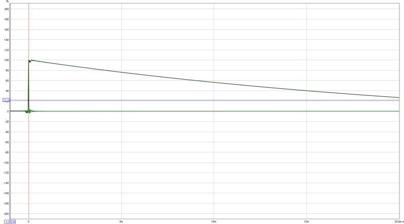
Impulse and STEP response
More closely zoomed in examples in my thread. In DRC I do not use a 4 cycle window. It's actually something like 6 cycles at 20 Hz, down to just over 4 cycles in mid frequencies and growing to 11 cycles at 20000 Hz.
Code:Minimum phase component single side sliding lowpass prefiltering. Input signal prewindowing. R - Initial lowpass convolution... R - Band: 0, 20.0 Hz, width: 13230, FIR, convolution... R - Band: 1, 25.2 Hz, width: 9821, FIR, convolution... R - Band: 2, 31.7 Hz, width: 7416, FIR, convolution... R - Band: 3, 40.0 Hz, width: 5668, FIR, convolution... R - Band: 4, 50.4 Hz, width: 4372, FIR, convolution... R - Band: 5, 63.5 Hz, width: 3395, FIR, convolution... R - Band: 6, 80.0 Hz, width: 2651, FIR, convolution... R - Band: 7, 100.8 Hz, width: 2078, FIR, convolution... R - Band: 8, 127.0 Hz, width: 1635, FIR, convolution... R - Band: 9, 160.1 Hz, width: 1289, FIR, convolution... R - Band: 10, 201.8 Hz, width: 1019, FIR, convolution... R - Band: 11, 254.0 Hz, width: 808, FIR, convolution... R - Band: 12, 320.4 Hz, width: 641, FIR, convolution... R - Band: 13, 403.7 Hz, width: 510, FIR, convolution... R - Band: 14, 508.2 Hz, width: 407, FIR, convolution... R - Band: 15, 640.9 Hz, width: 325, FIR, convolution... R - Band: 16, 809.0 Hz, width: 260, FIR, convolution... R - Band: 17, 1019.3 Hz, width: 209, FIR, convolution... R - Band: 18, 1281.3 Hz, width: 169, FIR, convolution... R - Band: 19, 1613.6 Hz, width: 137, FIR, convolution... R - Band: 20, 2045.3 Hz, width: 111, FIR, convolution... R - Band: 21, 2576.0 Hz, width: 91, FIR, convolution... R - Band: 22, 3251.6 Hz, width: 75, FIR, convolution... R - Band: 23, 4133.0 Hz, width: 62, FIR, convolution... R - Band: 24, 5222.6 Hz, width: 52, FIR, convolution... R - Band: 25, 6619.3 Hz, width: 44, FIR, convolution... R - Band: 26, 8280.5 Hz, width: 38, FIR, convolution... R - Band: 27, 10471.6 Hz, width: 33, FIR, convolution... R - Band: 28, 13284.2 Hz, width: 29, FIR, convolution... R - Band: 29, 16635.5 Hz, width: 26, FIR, convolution... F - Band: 30, 20000.0 Hz, width: 24, FIR, completed. Final allpass convolution...
And a totally different Excess phase window over only part of the frequency range from 20 Hz up to 500 Hz. Not as originally intended by Denis Sbragion 🙂.
Code:Excess phase component single side sliding lowpass prefiltering. Input signal prewindowing. R - Initial lowpass convolution... R - Band: 0, 20.0 Hz, width: 6547, FIR, convolution... R - Band: 1, 25.2 Hz, width: 4846, FIR, convolution... R - Band: 2, 31.8 Hz, width: 3652, FIR, convolution... R - Band: 3, 40.0 Hz, width: 2787, FIR, convolution... R - Band: 4, 50.4 Hz, width: 2147, FIR, convolution... R - Band: 5, 63.5 Hz, width: 1665, FIR, convolution... R - Band: 6, 80.0 Hz, width: 1299, FIR, convolution... R - Band: 7, 100.8 Hz, width: 1017, FIR, convolution... R - Band: 8, 127.1 Hz, width: 799, FIR, convolution... R - Band: 9, 160.2 Hz, width: 629, FIR, convolution... R - Band: 10, 201.8 Hz, width: 497, FIR, convolution... R - Band: 11, 254.4 Hz, width: 393, FIR, convolution... R - Band: 12, 321.0 Hz, width: 311, FIR, convolution... R - Band: 13, 404.2 Hz, width: 247, FIR, convolution... F - Band: 14, 500.0 Hz, width: 200, FIR, completed. Final allpass convolution...
The cycle dependant window in REW can be found here:

The raw impulse as measured in REW is used in DRC-FIR. I export it in REW at Mono, 32 bit and I use Normalise. Nothing else.
From there I've created batch files to do the rest of the work for me. Except changing the .wav export to .PCM format in CoolAudio.
This gives me a visual queue to see if everything is OK.
I generate both correction filters as well as simulated output in DRC. To be able to see it directly and compare to real measurements.
There is some confusion here. The benefit of a "vertically large transducer" is vertical directivity in the low frequency range. That is where multiple elements do act like a single transducer. When the individual elements become directional due to their size, the 6db/double distance summation falls down to 3db/dd, but you'd have to sit pretty close to the line to be able to hear it. If you sit more than a few feet away, it is not audible. This is where we disagree.
The horizontal directivity of the array is the directivity of the individual unit itself. With the B&G line transducer, its width is still comparable to the TC9 and I would fully expect it to go into beaming or breakup at a similar frequency. I don't want to speculate what happens to it in the vertical direction because I'm not familiar with the operation of the drivers. Does it still exhibit pistonic behavior? Or does it breakup into individual sources just like a cone or dome?
You're right...........using the RD75,40, etc as examples isn't really a good one as there's no model of how multiple full rangers interact vertically in the middle of the line or on plane with the listener.
Your horizontal approach with corner loading is the best possible scenario so kudos on that approach! There is a DIY horn loaded design out there somewhere from a guy in Finland but I can't find the link.
But your pistonic behavior reference is a good one as the driver reaches outside of it's diameter, pistonic behavior declines. Ring radiators and true ribbons excluded of course, but their operational range is limited of course. Acoustic lenses solve the problem but not practical for DIY efforts.....but lot's of work to be done!
The Speaker Dave line array paper linked earlier in this thread explains a lot of the behavior. The full range driver is just an element with a finite size. At wavelengths larger than its size, it is an omnidirectional radiator, and at wavelengths comparable to its size, its radiation becomes more forward in nature. So, the same model as in the paper can be used.
Yeah, my room affords the corner loading, which I'm grateful for. It limits the directivity to 90 degrees in the horizontal for frequencies where the Vifa is omnidirectional. But really, the key is the ceiling/floor and front wall reflections. Line arrays can solve some of these problems in a very elegant fashion.
If you can feed your brain with the right signals, a clean initial sound and low coloration by avoiding ceiling and front wall reflections, then it becomes a lot easier to follow the music and also get a good sense of depth.
It is highly debatable how we actually perceive sound. I believe the first wave front to be the most important (due to that precedence effect). So I did what I could to let it arrive as smooth as possible and in time! 😉
I guess it is, we can agree to disagree 😉
Wesayso, my setup is similar to yours. I use a custom multichannel DAC built using miniDSP products. It has 8 channels on i2s, IIRC. I have tried a connection similar to yours, i.e., select JAVA drivers in REW, output is JRiver, and input (mic) in EMU0204. Or, I have also done JAVA drivers, I/O set to EMU, then set EMU as the default in Windows, and use Wasapi Loopback in JRiver to pick up the sound and play it through the speakers. In both these setups, I get a funky impulse (you've seen it posted in your thread).
Now, here's my convoluted setup that gives the cleanest impulse:
1. Select ASIO drivers in REW. Choose I/O as EMU.
2. Take analog out from EMU and put it as input to a Behringer USB DAC.
3. Choose ASIO loopback in JRiver and get input from the Behringer (ASIO) to play it through the JRiver engine.
Question to both you and Pano: Do you guys calibrate the DAC/ADC chain? That is, loop the output to the input and measure. Holm has this feature, I'll have to check REW. But it may be one way to take the impact of the loopback out of the equation.
Now coming to the key issue: I think the reason your measurement looks so clean is the 4-cycle filter in REW. Where is this selection? I see the ERB, psychoacoustic and variable smoothing options, but haven't seen an option to set the variable window.
You're not setting up the loopback correctly - I wonder if doing it the way you were you were getting a second pulse looped back directly.
You need to set a "dummy" soundcard to default in the Windows menu (I use my onboard soundcard and it needs to have something plugged into it). REW should be Java and set output to the "dummy" device and input to your mic. Have JRiver set to output to your dac, and open the Live:Loopback feed. When you do measurements REW will send the pulse to the "dummy" device where JRiver will grab it and run it thru its' DSP before outputting to your normal DAC.
The new WDM driver works the same way, only it cuts out the "dummy" middle man by being a driver of its own. You set the Windows default device to the JRiver WDM, and you also set REW output to the WDM. Then you can make measurements with REW (or any other sw) and JRiver will act like the soundcard as far as Windows is concerned, and JRiver will output to your DAC. It works for many but on my main computer it's too buggy to use.
If you're not seeing the fdw in the impulse options then you don't have a newer version. Update to the latest build and you'll have it.
The Speaker Dave line array paper linked earlier in this thread explains a lot of the behavior. The full range driver is just an element with a finite size. At wavelengths larger than its size, it is an omnidirectional radiator, and at wavelengths comparable to its size, its radiation becomes more forward in nature. So, the same model as in the paper can be used.
Yeah, my room affords the corner loading, which I'm grateful for. It limits the directivity to 90 degrees in the horizontal for frequencies where the Vifa is omnidirectional. But really, the key is the ceiling/floor and front wall reflections. Line arrays can solve some of these problems in a very elegant fashion.
If you can feed your brain with the right signals, a clean initial sound and low coloration by avoiding ceiling and front wall reflections, then it becomes a lot easier to follow the music and also get a good sense of depth.
My concern here is the width of your baffle creating a "kink" in your effectively large conical horn where the baffle meets the wall. Obviously you're limited in the construction of the thing and you're measurements are pretty nice.
I guess it is, we can agree to disagree 😉
Did I miss something here? Seems like you guys know each other 🙂
You're not setting up the loopback correctly - I wonder if doing it the way you were you were getting a second pulse looped back directly.
You need to set a "dummy" soundcard to default in the Windows menu (I use my onboard soundcard and it needs to have something plugged into it). REW should be Java and set output to the "dummy" device and input to your mic. Have JRiver set to output to your dac, and open the Live:Loopback feed. When you do measurements REW will send the pulse to the "dummy" device where JRiver will grab it and run it thru its' DSP before outputting to your normal DAC.
The new WDM driver works the same way, only it cuts out the "dummy" middle man by being a driver of its own. You set the Windows default device to the JRiver WDM, and you also set REW output to the WDM. Then you can make measurements with REW (or any other sw) and JRiver will act like the soundcard as far as Windows is concerned, and JRiver will output to your DAC. It works for many but on my main computer it's too buggy to use.
If you're not seeing the fdw in the impulse options then you don't have a newer version. Update to the latest build and you'll have it.
But I've tried it that way, Nate. Using JAVA drivers and using JRiver as the output in REW and EMU mic in as the input. It gives me the funky impulse.
My concern here is the width of your baffle creating a "kink" in your effectively large conical horn where the baffle meets the wall. Obviously you're limited in the construction of the thing and you're measurements are pretty nice.
You are right about that. The baffle width is about 6". So, below 2250 Hz, it has 90 degree directivity. Above that it would be less than 90 degrees, maybe some reflections. But the baffle is as small as it can be given the depth of the drivers. I could fur the wall and push the whole thing in, but I'm pretty sure that would be outlawed by my wife.
Did I miss something here? Seems like you guys know each other 🙂
But I've tried it that way, Nate. Using JAVA drivers and using JRiver as the output in REW and EMU mic in as the input. It gives me the funky impulse.
Ha no we don't sorry....I just didn't want to start a side discussion about how we hear. I have a different idea than wesayo.
OK that's the WDM and like I said it's buggy for me. Have you tried the Loopback with the "dummy" soundcard? I didn't see that in your description. The WDM driver and the loopback are completely different. The Loopback is really similar to what you're doing now with a physical loopback, only it's done digitally. That said I really don't see anything wrong with what you're doing now other than it being a pain in the butt and you'd probably get goofy results if you wanted to do any dual channel measurements.
You are right about that. The baffle width is about 6". So, below 2250 Hz, it has 90 degree directivity. Above that it would be less than 90 degrees, maybe some reflections. But the baffle is as small as it can be given the depth of the drivers. I could fur the wall and push the whole thing in, but I'm pretty sure that would be outlawed by my wife.
I guess what I was driving at is diffraction due to the wave having to turn at the wall/baffle junction. Too bad about the wife 😉
I guess what I was driving at is diffraction due to the wave having to turn at the wall/baffle junction. Too bad about the wife 😉
The wave only has to turn when the dimension is comparable to the wavelength. Otherwise, it just won't "see" the edge. We don't complain about diffraction at 100 Hz, do we? Diffraction on a traditional baffle occurs when the wavelength is comparable to the baffle dimension. So, below 2250 Hz, it should be fine. Around there it might start to cause reflections. But still, it's much better than having it out in the room.
The wife is pretty awesome actually. Attended a couple of BAFs and tolerated much larger speakers when I didn't have a dedicated room. Just that my efforts tend to be butt ugly and she wouldn't want me to do things to the house. I wouldn't either 🙂
Ha no we don't sorry....I just didn't want to start a side discussion about how we hear. I have a different idea than wesayso.
We do have a place for that: http://www.diyaudio.com/forums/everything-else/284131-how-listen.html
Created to get us off of your thread, Nate 😉
The wave only has to turn when the dimension is comparable to the wavelength. Otherwise, it just won't "see" the edge. We don't complain about diffraction at 100 Hz, do we? Diffraction on a traditional baffle occurs when the wavelength is comparable to the baffle dimension. So, below 2250 Hz, it should be fine. Around there it might start to cause reflections. But still, it's much better than having it out in the room.
The wife is pretty awesome actually. Attended a couple of BAFs and tolerated much larger speakers when I didn't have a dedicated room. Just that my efforts tend to be butt ugly and she wouldn't want me to do things to the house. I wouldn't either 🙂
I guess I'm looking at it from the perspective that what you've created is a large conical horn. When we build a horn we don't make the horn entrance much larger than the driver exit/cone diameter. Doing so would cause rapid expansion then it would narrow again and cause a reflection. I would think that there would be reflections below where the piston diameter is controlling the pattern in your case. The driver is radiating omni-directionally and thus the baffle and finally the wall is controlling the pattern. The change in direction at the wall, to my way of thinking, will cause a reflection. I might do a model in AxiDriver and see what it shows. AD will make my model a true conical horn but looking at the field plot would be interesting I think.
Perhaps I'm overthinking it..........I've been wrong a time or two (or two dozen).
We do have a place for that: http://www.diyaudio.com/forums/everything-else/284131-how-listen.html
Created to get us off of your thread, Nate 😉
Lol, it was?
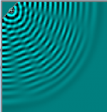
A horizontal line source can deal with this. Of course where the cones bring their own directivity this isn't necessary.I guess what I was driving at is diffraction due to the wave having to turn at the wall/baffle junction.
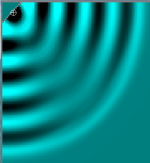
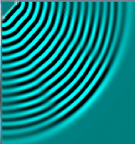
These are some sims with a point source.
Attachments


Interesting sims. Thanks Allen.
What are we looking at here? When you say line source, do you a mean horizontal line source in the sim? Or the line array? Are the different images showing different frequencies?
You're third image in post 52 is what I'm talking about. When the wavelength is larger than the baffle dimension, you can think of the entire baffle as a radiating diaphragm, kind of like a compression driver diaphragm in the throat of a horn.
That's right. A cylindrical wavefront calls for a line source. In this case this means a large vertical height (as you have now).
Looking purely in the horizontal it would come down to a point, which you have at lower frequencies.
The obvious problem is that it's not simple to mount the drivers outside the corner. Another concern is whether you trust the highest frequencies to be riding the room walls anyway, but the directivity of your full range drivers will benefit there.
By a line source in the horizontal I was referring to an overall plane array. A cylindrical waveguide is another version.
If you appropriately delay each driver, then you are essentially doing the curved line array, so it's a cheat. 🙂
I would think that the proof of good design in a line array is the impulse and step responses. As the theory goes, if you don't have a cylindrical waveform, but a series of point sources you should see a very lazy impulse and step responses even if you measure in an ideal location, with a small time window.
On the other hand, if these two signals are clean looking, you have proof of your line array functioning as a single driver. That's why I was so impressed by the impulse response if this design. Good job. 🙂
Erik
The frequencies are not distinctly quantified, I just chose a few that were larger/comparable/smaller than the baffle. LINKAhh cool thanks for those Allen. What frequencies are we looking at there, and what sw is that?
..and wouldn't necessarily mirror well, and I suspect that a straight array is a reasonable wavefront shape asymptote to an array with a virtually infinite dimension.If you appropriately delay each driver, then you are essentially doing the curved line array, so it's a cheat. 🙂
Attached is a new set of measurements that I made just now (extract the zip. The REW format was 13 MB after being zipped, so, the measurements are exported as text files). The first couple of measurements are those with loopback and calibration of the DAC/ADC loop. Below, I will explain each measurement in order:
1. Soundcard Loopback. REW Settings: JAVA drivers. EMU USB card selected for both input and output. In Windows, EMU is the default sound card. In JRiver, WASAPI loopback. Output of DAC from JRiver physically connected to mic input of EMU card.
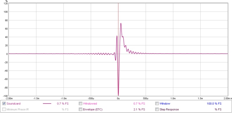
2. Soundcard Loopback. REW Settings: ASIO drivers. EMU USB card selected for both input and output. Output from EMU is physically connected to input of Behringer I/O USB DAC. In JRiver, use ASIO loopback and "listen" to input of Behringer. Output of DAC from JRiver physically connected to mic input of EMU card.
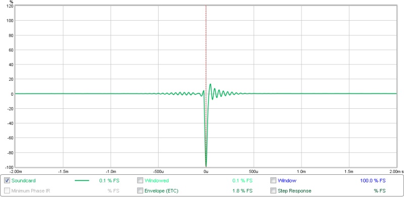
Clearly, the second option is much better. I used this to calibrate the loop in REW. Then did the following measurements.
3. Line array only (no sub) left uncorrected.
4. Line array only (no sub) right uncorrected.
5. Line array only (no sub) left corrected.
6. Line array only (no sub) right corrected.
These measurements look much better. The impulse is clean for both channels.
1. Soundcard Loopback. REW Settings: JAVA drivers. EMU USB card selected for both input and output. In Windows, EMU is the default sound card. In JRiver, WASAPI loopback. Output of DAC from JRiver physically connected to mic input of EMU card.
2. Soundcard Loopback. REW Settings: ASIO drivers. EMU USB card selected for both input and output. Output from EMU is physically connected to input of Behringer I/O USB DAC. In JRiver, use ASIO loopback and "listen" to input of Behringer. Output of DAC from JRiver physically connected to mic input of EMU card.
Clearly, the second option is much better. I used this to calibrate the loop in REW. Then did the following measurements.
3. Line array only (no sub) left uncorrected.
4. Line array only (no sub) right uncorrected.
5. Line array only (no sub) left corrected.
6. Line array only (no sub) right corrected.
These measurements look much better. The impulse is clean for both channels.
Attachments
Last edited:
Looks like you've got it going. 
FWIW, yes, I do calibrate the sound card because it's so easy to do so. Not really needed for speaker work, as the sound card is so much flatter and more extended than any speaker or mic I'll ever own.
So. You have 24 drivers per side? All butted up tight against each other on the flat flange? That should come out to 7ft long. If the cones are so close to each other, I wonder what effect that has on comb filtering. At longer wavelengths it shouldn't be bad, as the cones are almost touching each other.
- Home
- Loudspeakers
- Multi-Way
- Corner Floor-to-Ceiling Line Array Using Vifa TC9