Hi all, anything news? I am exited to hear from Valery post 56🙂
I guess I'm not the only one itching to build this one.😀
Well, I don't really like to have those transistors at the drivers' bases... At 4.5A per output pair protection will shut-down the amp.
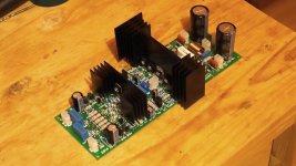

Wow, those are some serious heatsinks.
Do those small transistors dissipate that much heat?
Well, that's definitely an overkill here. I will probably change them to something smaller and simpler over the time. Good for testing though 🙂
Test it with what you have at your hand now.😱Well, that's definitely an overkill here. I will probably change them to something smaller and simpler over the time. Good for testing though 🙂
("CFA" schematic - taken from a well known amplifier manufactor)
Look how this VAS is coupled in positive Q605 + Q609 like a CCS?
How you seen this before?
R629 + R630 are base resistors to three stage EF outputstage.
Look how this VAS is coupled in positive Q605 + Q609 like a CCS?
How you seen this before?
R629 + R630 are base resistors to three stage EF outputstage.
An externally hosted image should be here but it was not working when we last tested it.
Last edited:
Not just that, Q24, Q25 driven CCS for input buffer in VAS bias feedback, could also eliminate output DC offset since they influence opposite drive side, very nice idea.Here goes v02.
I have also added the "BIAS" plug for overcurrent sensor - in the middle of PCB. Size is the same, just "cleaned up" some space 🙂
Have fun!

Maybe C35, C36 are little too low on value, also R5, R8 should be much lower (2,5 k) providing 1 mA input buffer bias, waiting for measurements. 😉
Not just that, Q24, Q25 driven CCS for input buffer in VAS bias feedback, could also eliminate output DC offset since they influence opposite drive side, very nice idea.
Maybe C35, C36 are little too low on value, also R5, R8 should be much lower (2,5 k) providing 1 mA input buffer bias, waiting for measurements. 😉
Thank you LC 😉
This is what I mentioned as an "elegant implementation" of the CCSs in post #51 🙂
Just tested with no output transistors and no load.
Runs well. The funny thing - you were right, probably it will run fine with no servo, I'llll try it later - there's no power-on blip at the output at all. Not a short one or low-level one - just nothing 😱
Moving forward...
Measurements!
OK, finally - testing and measurements.
I tested it with MJL21193G/21194G at the output.
Only front-end to-92 transistors are roughly matched (within more or less 20%), all the rest - no matching.
First of all - it's very stable. No sign of any kind of oscillation whatsoever.
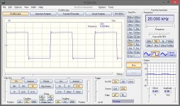
I have checked the offset with no servo - gives +230mV. Not bad, assuming this is a CFA with no DC decoupling cap. Servo makes it less than 5mV - you can see it at the first picture.
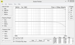
Bode plot shows wide bandwidth (close to 1MHz at -3db) with excellent phase response(-2.3 degrees @ 20KHz). Fast one.
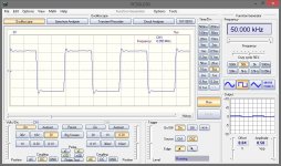
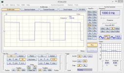
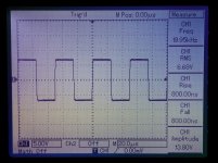
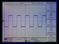
Square response - not bad, but there is some overshoot, clearly visible at high frequencies, with a couple of fading revolutions before it settles. This is something I don't like and I'm going to investigate it deeper.
The other point that slightly concerns me - thermal stability. I need to make the second heatsink (with the drivers) much smaller. They are barely warm and, I suppose, thermal feedback is not as effective as it could be with the smaller one. Output pairs run at 30-35mA with no signal - rather cold when idle, warming up at higher swing.
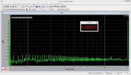
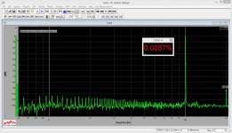
THD - not bad, higher order harmonics concern me a bit, however absolute level is low enough and I doubt, this is somehow related to the overshoot, mentioned above. There is an interesting dependency though - frequency wise, minimum is at 5-10KHz, slightly increasing towards the lower frequencies, as well as towards the higher ones.
Intermodulation is good.
Did some listening - no surprise, very natural reproduction, solid, balanced, natural. I like it even "as is".
In overall, it works fine, although I'm going to fine-tune it a bit during the nearest days.
Good ideas are welcome 😉
Cheers,
Valery
OK, finally - testing and measurements.
I tested it with MJL21193G/21194G at the output.
Only front-end to-92 transistors are roughly matched (within more or less 20%), all the rest - no matching.
First of all - it's very stable. No sign of any kind of oscillation whatsoever.
I have checked the offset with no servo - gives +230mV. Not bad, assuming this is a CFA with no DC decoupling cap. Servo makes it less than 5mV - you can see it at the first picture.
Bode plot shows wide bandwidth (close to 1MHz at -3db) with excellent phase response(-2.3 degrees @ 20KHz). Fast one.
Square response - not bad, but there is some overshoot, clearly visible at high frequencies, with a couple of fading revolutions before it settles. This is something I don't like and I'm going to investigate it deeper.
The other point that slightly concerns me - thermal stability. I need to make the second heatsink (with the drivers) much smaller. They are barely warm and, I suppose, thermal feedback is not as effective as it could be with the smaller one. Output pairs run at 30-35mA with no signal - rather cold when idle, warming up at higher swing.
THD - not bad, higher order harmonics concern me a bit, however absolute level is low enough and I doubt, this is somehow related to the overshoot, mentioned above. There is an interesting dependency though - frequency wise, minimum is at 5-10KHz, slightly increasing towards the lower frequencies, as well as towards the higher ones.
Intermodulation is good.
Did some listening - no surprise, very natural reproduction, solid, balanced, natural. I like it even "as is".
In overall, it works fine, although I'm going to fine-tune it a bit during the nearest days.
Good ideas are welcome 😉
Cheers,
Valery
Attachments
-
 04-CFA-CFP-IMD-14-15KHz.JPG202 KB · Views: 194
 -
 03-CFA-CFP-THD-020KHz.JPG197.2 KB · Views: 188
 -
 03-CFA-CFP-THD-010KHz.JPG197.8 KB · Views: 229
 -
 03-CFA-CFP-THD-001KHz.JPG206.4 KB · Views: 258
 -
 02-CFA-CFP-SQR-100KHz.JPG138.4 KB · Views: 223
 -
 02-CFA-CFP-SQR-050KHz.JPG138.9 KB · Views: 524
 -
 02-CFA-CFP-SQR-020KHz.JPG138.2 KB · Views: 532
 -
 02-CFA-CFP-SQR-001KHz.JPG133.6 KB · Views: 555
 -
 01-CFA-CFP-Bode-01.JPG69.5 KB · Views: 573
 -
 00-DSC03449.JPG202.7 KB · Views: 578
It's not surprising the drivers aren't warming up with that monster heat sink! Should Q15 be tracking driver temperature or output device temperature?
Definitely some experimentations with caps:
- C11, C12 too high or eliminate
- C8 too high or eliminate
- C9, C10 trimm to set
- C35, C36 1 uF or higher
L.C.
- C11, C12 too high or eliminate
- C8 too high or eliminate
- C9, C10 trimm to set
- C35, C36 1 uF or higher
L.C.
It's not surprising the drivers aren't warming up with that monster heat sink! Should Q15 be tracking driver temperature or output device temperature?
In case of CFP output arrangement it makes sense to track the drivers. Heatsink definitely must be smaller. Otherwise, it's like trying to boil a swimming pool with tea boiler 🙂
Found the "sweet spot" yet?
Well, I have adjusted compensation, so that I get decent squares, but now the problem is - as soon as signal frequency exceeds 200KHz, the drivers and outputs heat-up significantly, and around 700-800KHz I get shoot-through (both output shoulders are open). OPS seems to be too slow...
Killed some outputs 🙁
Attachments

Well, I have adjusted compensation, so that I get decent squares, but now the problem is - as soon as signal frequency exceeds 200KHz, the drivers and outputs heat-up significantly, and around 700-800KHz I get shoot-through (both output shoulders are open). OPS seems to be too slow...
Killed some outputs 🙁
Do you think output transistor for CFP must be fast transistor (high fT) or it happen only on CFA topology?
I was wondering if those old MJL21193/4 were going to be too slow. They've been a problem in some of the Slewmonsters too. I've got a couple fresh rails or NJW1302/3281s waiting to try out on this one.
Last edited:
Builder thimios fried his 21193/4's with the first CFA. 🙁
He uses 35mhz Sanken's now - says they are the "champs". They survive
cooked zoble's and all. 😱
BTW ... Nice build ,Valery.
PS - this would happen on VFA/CFA , EF3 or CFP. The MJL's are only good for 220pF compensated
"elliot sound" sub amps.
OS
He uses 35mhz Sanken's now - says they are the "champs". They survive
cooked zoble's and all. 😱
BTW ... Nice build ,Valery.
PS - this would happen on VFA/CFA , EF3 or CFP. The MJL's are only good for 220pF compensated
"elliot sound" sub amps.
OS
Last edited:
The funny thing - I'm testing with no output transistors now (and no load except NFB, which is ok for these 2 pairs of drivers).
Giving it 2KHz square, 13.4V amplitude at the output - excellent waveform, no problem. Drivers are cold. Half an hour in this state - still cold.
Increasing the frequency to 200-500KHz (same amplitude). Within a minute the drivers get hot. No oscillation or other artifacts on the scope. How is it possible? It's not the case with my VFAs - they run at 500KHz same as at 1KHz.
I agree, MJL21193/21194 are slow (fT = 4MHz), but I have tried NJW0281/0302 with fT = 30MHz... same result.
Well, I don't want to connect the output transistors until I make the drivers cold enough at 200KHz...
Very interesting experience
- Status
- Not open for further replies.
- Home
- Amplifiers
- Solid State
- Cool simple "clean" CFA