Benefits of this kind of amp are especially noticeable at "difficult" material, like Gordon Goodwin's Big Phat Band. Lots of instruments - trumpets, saxophones, drums, cimbals in combination with well-distinguished piano and tight base...
Thanks ValeryHi LC, R26 voltage drop goes like this:
10s - 0.79V
30s - 0.80V
1m - 0.82V
2m - 0.84V
3m - 0.85V
4m - 0.86V
6m - 0.87V
9m - 0.88V and then it stays at this level
I simulated higher VAS current (14mA with 3.3K input buffer CCS emitter resistors) - it doesn't show any advantages... almost 9mA seems to be enough for driving this OPS smoothly. I will probably try it live a bit later, just to make sure...
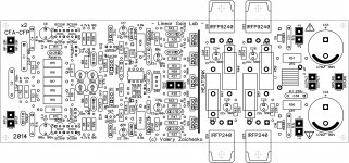
Attached is the schematic "as built" for now.
Updating the PCB 😉
Cheers,
Valery
I see many caps have left the building, also some are higher in value, as predicted.😉
C13 should be 10 uF since it influence SQ quite a bit.

VAS gain also plays important role in shaping SQ. 😎
Trimming some resistors would probably eliminate DC servo too. 🙂
All in all nice CFA amp.
L.C.

Is it still lively at low volume levels? I find most amps go flat.
Are you sure it's not subjective perception, caused by the fact that human's ear hears highs and lows not so good at low volumes? Also, some amplifiers, especially if it's a slightly under-biased class-AB ones, have got noticeable THD increase at low power, so that at 10W or higher it performs better than at 1W or lower. Just wondering 🙂
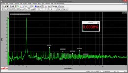
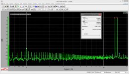
This one has got THD decrease at low volumes, and THD is almost constant throughout the audio bandwidth (although the profile contains more visible components than most of my other designs)...
Thanks Valery
I see many caps have left the building, also some are higher in value, as predicted.😉
C13 should be 10 uF since it influence SQ quite a bit.
VAS gain also plays important role in shaping SQ. 😎
Trimming some resistors would probably eliminate DC servo too. 🙂
All in all nice CFA amp.
L.C.
Thanks LC, I will look closer at C13 and will test some 14mA VAS on the prototype (simulation gives very rough estimation with regards to SQ)...
And yes - compensation became simpler but harder to keep the creature under control 🙂 I like higher C35, C36 as well, as you suggested

Are you sure it's not subjective perception, caused by the fact that human's ear hears highs and lows not so good at low volumes? Also, some amplifiers, especially if it's a slightly under-biased class-AB ones, have got noticeable THD increase at low power, so that at 10W or higher it performs better than at 1W or lower. Just wondering 🙂
This one has got THD decrease at low volumes, and THD is almost constant throughout the audio bandwidth (although the profile contains more visible components than most of my other designs)...
I've noticed a definite difference in higher frequency reproduction at lower volume levels in many amps. I have 105db efficient speakers so I usually play at a lower volume level than most. My hearing is damaged too so it may be more pronounced for me. I guess I need to try it out and see for myself.
... and will test some 14mA VAS on the prototype (simulation gives very rough estimation with regards to SQ)...
I was thinking about VAS gain not bias current, meaning changing VAS emitter resistors to lower value. Try first with 10 ohm and hear if the difference is noticable.
I was thinking about VAS gain not bias current, meaning changing VAS emitter resistors to lower value. Try first with 10 ohm and hear if the difference is noticable.
Aaaaah! I see now )
Increased VAS gain
Tried decreasing R26, R29 to 22R, leaving all the rest as is.
VAS current comes close to 40mA - cascodes are running pretty hot.
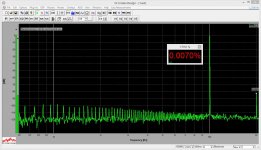
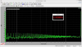
With R26, R29 = 47R, VAS current is 18.5mA. Optimal quiescent current for the output pairs is 35mA. Re-measured THD / IMD.
No noticeable change in listening tests.
Sounds equally good 🙂
Tried decreasing R26, R29 to 22R, leaving all the rest as is.
VAS current comes close to 40mA - cascodes are running pretty hot.
With R26, R29 = 47R, VAS current is 18.5mA. Optimal quiescent current for the output pairs is 35mA. Re-measured THD / IMD.
No noticeable change in listening tests.
Sounds equally good 🙂
Attachments

Hi Guys,
I'm planning on ordering some boards for this amp. I have to order some extras. If any of you are interested, Please PM me and let me know so I will know how many to get.
Blessings, Terry
I'm planning on ordering some boards for this amp. I have to order some extras. If any of you are interested, Please PM me and let me know so I will know how many to get.
Blessings, Terry
Benefits of this kind of amp are especially noticeable at "difficult" material, like Gordon Goodwin's Big Phat Band. Lots of instruments - trumpets, saxophones, drums, cimbals in combination with well-distinguished piano and tight base...
That's the benefit of high slew rate amplifiers, either CFA, VFA or opamps. Very audible but many say that more than "theoretically adequate" SR is not necessary 🙄
One of a few things that interest me from this thread is the CFP output. I have no success using (bipolar) CFP in a CFA. Some people said: using slow output (topology) in a fast amp is not logical (defies the purpose)...
Tried decreasing R26, R29 to 22R, leaving all the rest as is.
VAS current comes close to 40mA - cascodes are running pretty hot.
With R26, R29 = 47R, VAS current is 18.5mA. Optimal quiescent current for the output pairs is 35mA. Re-measured THD / IMD.
No noticeable change in listening tests.
Sounds equally good 🙂
To preserve VAS bias, R10, R13 have to be decreased at the same time as R26, R29.
Are R14, R20 neccessary for proper compensation, without them amp is unstable? R3, R4 are somehow strange too.
Yes, I know. However simulations don't show any significant improvement when I simultaneously decrease R10, R13 and R26, R29.
Those base stoppers are there on "just in case" basis 🙂 In fact, jumpering R3, R4 and decreasing R14, R20 - worth trying...
Those base stoppers are there on "just in case" basis 🙂 In fact, jumpering R3, R4 and decreasing R14, R20 - worth trying...
One of a few things that interest me from this thread is the CFP output. I have no success using (bipolar) CFP in a CFA. Some people said: using slow output (topology) in a fast amp is not logical (defies the purpose)...
Well, CFP is a "dangerous creature", especially in CFA design, but this MosFET arrangement runs smoothly and sounds great. I'm especially happy with this "dual-CFP" arrangement. Auditioning it for a few days already 😛
Is the schematic in post 93 still accurate?
Minor amendments:
R26, R29 = 47R
R28 = 750R
All the rest components are as shown in post 93. Quiescent current for the output transistors is 35mA per pair - at normal listening volumes they run barely warm.

- Status
- Not open for further replies.
- Home
- Amplifiers
- Solid State
- Cool simple "clean" CFA