Eva said:Separate supplies are a big no-no, they bring plenty of new problems. The amount of components and circuit traces attached to the switching node should be kept to an absolute minimum due to capacitive coupling to modulators and analog input stages
If you look at that trafo diagram, it also contains an extra screen winding just to eliminate capacitive coupling between primary and secondary...... and also the trafo must be mounted closed to switching node so that RF emissions could be kept low.....
A screen does not eliminate capacitive coupling, it only transfers coupling to another circuit node, and this is done at the expense of increasing capacitance too. A common-mode filter wound single layer on a toroid is far more efficient.
When switching dV/dt slopes approach 10V/ns you can no longer expect the shield to have uniform potential across it. You can't even expect the PCB track connecting the shield to somethere to be a low impedance path.
A few nH of PCB track inductance and and few pF of capacitance (plus internal transformer distributed inductance and capacitance) is all what you need to build a nice RF resonator that will get excited on every switching transient. This ia a big no-no unless you like ringing. I like clean waveforms.
I think Eva's point with capacitive coupling is quite valid.
Shooting capacitive peaks throughout the entire system is not really promising...
And definitely... yes, even in my fat bottomed 1kW buddy I am watching 15V/ns....
....so...?
Back to bootstrapping? With fat cap? And input signal limitation that never allows bad clipping ? And may be even a floating 7812? ...would be quite unpleasant in part count, but probably easy to handle ... and if someone really goes for 7812, then the bootstrap cap could be reduced again ...hm...
Which diodes do you propose for bootsrapping?
Up to now I got the best results with these two versions:
-BAV21
-Schottky (for higher rails may be two in series)
Or workhorse's approach?
Attachments
My experience is that a big bootstrap capacitor is enough to keep the high side gate drive voltage reasonably constant, provided that the low side supply is regulated. The big capacitor seems to account very well for the changes in peak to average ratio of the current through the bootstrap diode and resistor and audio signals spend very little time near the rails.
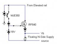
If I was asked for permanent high side turn-on capability, I would add a 1mA current source from an elevated +24V (or so) rail, made with a PNP transistor having suitable Vce (up to 300V with standard MPSA92) and both a high value inductor and a low value one in series with the collector (probably one self-resonating in the 100Mhz range and other in the 30Mhz range) to keep the current constant during switching spikes and the spikes themselves away from the PNP.
This may not seem obvious for everybody, but the bootstrap capacitor is charged in every switching transient, so the high side gate drive current itself is inherently guaranteed (particularly if we consider that both self-oscillating amplifiers and gate driver ICs impose a limit on how narrow the switching pulses can become when the output approaches the rails). So all what you have to compensate for is the quiescent current of the high side driver, which is usually 1mA worst case maximum for IR parts.
Anyway, my favourite method is a timer pulling the high side drive signal low during 1..5us, everytime it stays high for 100..500us. This simple approach blows away all the complex supplies used by others.
ChocoHolic said:I think Eva's point with capacitive coupling is quite valid.
Shooting capacitive peaks throughout the entire system is not really promising...
And definitely... yes, even in my fat bottomed 1kW buddy I am watching 15V/ns....
....so...?
Back to bootstrapping? With fat cap? And input signal limitation that never allows bad clipping ? And may be even a floating 7812? ...would be quite unpleasant in part count, but probably easy to handle ... and if someone really goes for 7812, then the bootstrap cap could be reduced again ...hm...
Which diodes do you propose for bootsrapping?
Up to now I got the best results with these two versions:
-BAV21
-Schottky (for higher rails may be two in series)
Or workhorse's approach?
Probably not economical for a mass-produced design, but for a one off DIY project a little $10 PCB mount DC-DC converter is the way to go.
Hi Eva!
You wrote you use ferrite beads serial with MOSFETs' gate. I think in this way every MOSFET can switch on his counterpart through Cgd.
You wrote you use ferrite beads serial with MOSFETs' gate. I think in this way every MOSFET can switch on his counterpart through Cgd.
ChocoHolic said:
Which diodes do you propose for bootsrapping?
Up to now I got the best results with these two versions:
-BAV21
-Schottky (for higher rails may be two in series)
For this 100V circuit I have used 1N4148 without trouble. There is a low side diode too that ensures matched drive voltages and switching times. I think that anything storing little reverse recovery charge is OK.
G.Kleinschmidt said:
Probably not economical for a mass-produced design, but for a one off DIY project a little $10 PCB mount DC-DC converter is the way to go.
This is not DIY attitude at all, this is big $$$ company engineer attitude. A DIY-er will find a clever way to do it (or to avoid doing it). Those (expensive unless surplus) potted PCB-mount DC-DC converters are routinely used by "engineers" as ideal building blocks, particularly in industrial appliances. They are far from ideal, though, and noise problems arise when this fact is overlooked...
Don't you know that even the models with isolated outputs have substantial capacitance from the outputs to the input? There is transformer capacitance, say 100pF, and 1nF or more for EMI filtering purposes... In other words: Useless for our application without an additional common-mode filter (not to mention that the outputs should not be switched back and forth with high dV/dt because this disturbs internal feedback optocoupler resulting in substantial deviation from the expected output voltage, but only when the thing is switching 😀😀😀 ).
Yes, I have seen people using these DC-DC bricks for floating gate supplies, and I prefer not to think too much about the resulting ringing and EMI havoc because it scares me... But then again, these are the kind of people that don't use oscilloscopes too much, so they can live with massive 20Mhz ringing... Then, passing EMC is a matter of adding three or four common-mode filters at the input 😀😀😀
Gyula said:Hi Eva!
You wrote you use ferrite beads serial with MOSFETs' gate. I think in this way every MOSFET can switch on his counterpart through Cgd.
Wrong. You are thinking with a too simple circuit model in mind.
Eva said:This is not DIY attitude at all, this is big $$$ company engineer attitude. A DIY-er will find a clever way to do it (or to avoid doing it). Those (expensive unless surplus) potted PCB-mount DC-DC converters are routinely used by "engineers" as ideal building blocks, particularly in industrial appliances. They are far from ideal, though, and noise problems arise when this fact is overlooked...
Don't you know that even the models with isolated outputs have substantial capacitance from the outputs to the input? There is transformer capacitance, say 100pF, and 1nF or more for EMI filtering purposes... In other words: Useless for our application without an additional common-mode filter (not to mention that the outputs should not be switched back and forth with high dV/dt because this disturbs internal feedback optocoupler resulting in substantial deviation from the expected output voltage, but only when the thing is switching 😀😀😀 ).
Yes, I have seen people using these DC-DC bricks for floating gate supplies, and I prefer not to think too much about the resulting ringing and EMI havoc because it scares me... But then again, these are the kind of people that don't use oscilloscopes too much, so they can live with massive 20Mhz ringing... Then, passing EMC is a matter of adding three or four common-mode filters at the input 😀😀😀
Oh dear.
What a lot of silly generalizations. I use DC-DC converters a lot, mostly in sensitive scientific instrumentation where EMI issues are 100 times more relevant than in class D audio amplifier design and I use oscilloscopes that probably cost more than your house.
I'm not sure how many "engineers" would consider a DC-DC converter an "ideal building block" either. Perhaps you are talking about immaginary engineers?
WRT inter winding capacitance and dv/dt switching, these are valid concerns, but with some pretty simple filtering techniques they are far from insurmountable. Heck, I’ve got my 1kV AM transmitter plate modulator class D amp operating now with its DC-DC converter floating supplies and the waveforms are as clean as a whistle - far cleaner than anything you’ve posted here lately. Amazing, I guess......................
Bye bye.
Eva said:So it wasn't a DIY-er thing at all 😀
No, the class D thing was DIY. The converter cost me about $10 AUD - less than the cost of just one of the PSU filter electrolytics.
I'm not having to eat jam sandwiches for a month or anything.................
Then you can use it with a $10 single-layer-wound toroid common-mode filter 😉 But someone doing so high tech scientific electronics should not have overlooked the extreme dV/dt and in-out capacitance stuff 😉
Eva said:Then you can use it with a $10 single-layer-wound toroid common-mode filter 😉 But someone doing so high tech scientific electronics should not have overlooked the extreme dV/dt and in-out capacitance stuff 😉
I didn't overlook the dv/dt in-out capacitance stuff. With the converter (unregulated output) and input filtering I'm using, it isn't an issue.
G.Kleinschmidt said:I didn't overlook the dv/dt in-out capacitance stuff. With the converter (unregulated output) and input filtering I'm using, it isn't an issue.
Looked at your signature lately?

I use much of the same overpriced equipment, and still find Eva's designs worthwhile. Let's stick with the thread's intent, please.
EnvisionAudio said:Let's stick with the thread's intent, please.
Yes, please. Keep a good thread clean. I thought both of you were more professional than to argue so pointlessly.
EnvisionAudio said:
Looked at your signature lately?
I use much of the same overpriced equipment, and still find Eva's designs worthwhile. Let's stick with the thread's intent, please.
I did not criticise Eva’s design or say that it was not worthwhile. The topic drifted to floating supplies, I mentioned (inoffensively, I thought) an alternative method, which has worked well for me.
Adios. I’m out of here.
Eva said:But then again, these are the kind of people that don't use oscilloscopes too much, so they can live with massive 20Mhz ringing...
I live with some very minor 3MHz ringing on one of my designs - it exceeds the cost of many components to try and eliminate it. After a while, the use of the oscilloscope becomes an annoyance where time, cost and conscience seem to battle it out until the bitter end. 😀
But we press on.
G.Kleinschmidt said:
I did not criticise Eva’s design or say that it was not worthwhile. The topic drifted to floating supplies, I mentioned (inoffensively, I thought) an alternative method, which has worked well for me.
Adios. I’m out of here.
What you call inoffensive is what many see pedantic. Personality disorders aside, the points Eva brought up regarding the use of a "potted block" for a floating gate-drive supply are not only relevant but exceptionally forward-thinking. I can't think of a reasonably well designed $10AUD "brick" from any supplier. Either you're making it up or you don't understand. I leave this case alone now.
ChocoHolic said:Or workhorse's approach?
Thats Better!!
Eva said:If I was asked for permanent high side turn-on capability, I would add a 1mA current source from an elevated +24V (or so) rail, made with a PNP transistor having suitable Vce (up to 300V with standard MPSA92) and both a high value inductor and a low value one in series with the collector (probably one self-resonating in the 100Mhz range and other in the 30Mhz range) to keep the current constant during switching spikes and the spikes themselves away from the PNP.
A 1mA-5mA current source still can't be able to supply the required charge to enable the cap voltage to remain constant or not letting to fall below 10V, if the amp is subjected to 22dBU overdrive.......I have done it on Charles recommendation........but no success so far...
A SFbuffer is just what is needed to achieve the 0-100% dutycycle approach......for high side
Attachments
- Status
- Not open for further replies.
- Home
- Amplifiers
- Class D
- Cool and small 2x150W class D full-range car amplifier