Somehow it still escapes me which hard advantages the rather complicated diffamp approach has on the very simple and nicely working method mentioned here..
So, what is the reason to engage much more parts, complexity and a more demanding power supply than obviously necessary to do the job? Just because it can be done that way, too?
Regards,
Tom Schlangen
So, what is the reason to engage much more parts, complexity and a more demanding power supply than obviously necessary to do the job? Just because it can be done that way, too?
Regards,
Tom Schlangen
Hey Tom,
From post 56 to 68 your concept is used, albeit in modernised form. So forget the diff if you don´t like it. But your concept gets more complicated when you have to add the necessary CF to get low Zout. The one in the thread you showed had a Zout in the ballpark of 25kohm.
Which is the most complicated: The CF-diff circuit in post 43 or the result of the concept you adviced in post 68😉?
By the way what happened to your nice website with the triode-strapped pentodes? If was kind of reference library for me.
Hi Lars,
Ah, yes, at the combined output. On the other hand, one can bomb down Zo massively by just using a tube with higher gm, a few mA more going, and tweaking resistors (including the ones in the adder network).
But if one really needs even less Zout than that - okay.
Regards,
Tom Schlangen
The one in the thread you showed had a Zout in the ballpark of 25kohm.
Ah, yes, at the combined output. On the other hand, one can bomb down Zo massively by just using a tube with higher gm, a few mA more going, and tweaking resistors (including the ones in the adder network).
But if one really needs even less Zout than that - okay.
Regards,
Tom Schlangen
I defy anyone to explain this. Not sure I understand it myself...
Output Z appears to be 275ohms? At least at that load seems
to drag the nominal output voltage swing down 50%. Gets a
bit of 2nd harmonic when loaded real crazy low like that... No
bad harmonics at reasonable loads.
Also seems unaffected by grounding either one end of the source.
Good sign that its a true differential. Near completely unaffected
when challenged with 1V of power supply ripple. I can't see any
120Hz in the output at all.
Attachments
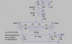
I had the zany thought that a plate follower needs voltage gain
for the feedback to knock down the error. So if 6DJ8 is good,
maybe a cascode plate follower is even better?
Then really went off the deep end, asking what iff??? iFFFFF????
What if we make the top device double as a cathode follower?
---------------------------------------------------
Output swing simulated 2.75V P-P or +/-1.375 take your pick...
I didn't test what signal level might drive the input(s) to clipping.
The node between R3 and R4 is a virtual ground, so the -end
of V1 sees a 47K load.
The node between R1 and R2 swings in unison with the inputs,
and appears to have a high impedance! Thus R5 was added to
load the +end of V1 with a similar 47K to ground.
Attachments
kenpeter,
The dac is totally wrong. It has +2,5V at each output with ref to ground. So use my DAC-model instead. Also your voltage source with 0,7Vrms ripple is unrealstic!
Otherwise I don´t understand anything of it !
!
The dac is totally wrong. It has +2,5V at each output with ref to ground. So use my DAC-model instead. Also your voltage source with 0,7Vrms ripple is unrealstic!
Otherwise I don´t understand anything of it
!With ref to an irrelevant sandy ground, +2.5V yes...
But not necessarily to the ground of this tube stage.
The link is differential...
Everything else I have not explained, is exactly the
same theory of operation as the plate follower you
guys have previously drawn.
But not necessarily to the ground of this tube stage.
The link is differential...
Everything else I have not explained, is exactly the
same theory of operation as the plate follower you
guys have previously drawn.
Rebiased to sandy ground level.
The only part I can't fathom is why the PSRR is so good?
I can see both 1000Hz and 120Hz ripple current through
the totem, yet the output voltage signal is ripple free.
I am not sure how the ripple canceled? It wasn't anything
intentional or I'd be taking credit!
The only part I can't fathom is why the PSRR is so good?
I can see both 1000Hz and 120Hz ripple current through
the totem, yet the output voltage signal is ripple free.
I am not sure how the ripple canceled? It wasn't anything
intentional or I'd be taking credit!
Attachments
Oh, oh, I see it now! I pulled a Broskie without even realizin...
Just like the output stage of an Aikidio.
I just upped it to 10V power ripple, all quiet on the output.
Except for the signal output whats supposed to be there.
Can't be right, no real triodes will ever match that good.
Just like the output stage of an Aikidio.
revintage said:Also your voltage source with 0,7Vrms ripple is unrealistic!
I just upped it to 10V power ripple, all quiet on the output.
Except for the signal output whats supposed to be there.
Can't be right, no real triodes will ever match that good.
OK, here's with some real stOOpid abuse.
Drive the DAC outputs full swing, tack on
another 5V common mode noise at 450Hz...
Starve the whole circuit 100V lower than
"normal", and 5V of Power Ripple at 120Hz.
So what happens with all this garbage in?
Is it broke yet? Nope! not even...
Common mode rejection looks to be about -35db,
and the power noise is still nowhere to be seen.
I've never seen a tube circuit this hard to knock
out of tune... There must be outrageous amount
of local feedback? Whatever, its working???
--------------------------------------------
I swear I didn't design this "good" on purpose.
All monkeys must eventually type Shakespeare.
Credit to the Devil and dumb luck.
Attachments
You gotta be kiddin me.... This thing works fine on 48V?
Don't seem to tolerate much other simultaneous abuse,
but 48V supply definitely works. With no circuit changes
to accomodate the decrease.
Now I can't seem to load the ouput any lower than 4K7,
or it distorts pretty bad. And below 2K2 the sim hangs...
I can't verify the actual load impedance of half amplitude,
in this state of starvation, but its sure lower than 2K2.
It works very nice with loads above 4K7.
I had the DAC outputs swing 2V apiece, and no common
mode or power supply noise in this run.
--------------------------------------------------------
Works even better (at48V), replacing plate resistor with
a choke. I tried 4H 100ohms, driving 1K loads no probs.
Very nice, Ken,
Adding the signals together in the totem pole is brilliant!
That plus balanced ripple gets you some kind of award...
Plate feedback and that 47K bridge makes it all work.
I keep getting smoke out my ears when I try to work out
the gain and balance equation. Iterate with spice?
The triple play would be adding balanced input impedance
Plate feedback is da stuff for circuits using high-gm low-rp tube
circuits.
Michael
The triple play is there. Both ends see 47K.
The difference node is near zero impedance.
Difference input sees 47K to a virtual ground.
Driven in true diffferential, the sum node is
very high impedance. Sum input driving into
a voltage node the same as itself. I added
a 47K appendix to ground on the left edge,
specifically to make the input Z's balance.
It also completes a circuit to bleed the grid.
DC loading might be a little different, but
as long as the DACs aren't bothered by it,
the tube stage don't mind.
😀
oh man ... i just wanted an idea for a nice little tube output stage 😀 😀 🙂............
thnx for the effort........
oh man ... i just wanted an idea for a nice little tube output stage 😀 😀 🙂............
thnx for the effort........
revintage - tha is exactly what i had in my mind.... to use exactly that circuit in your previous post...........
Hi Revintage
Is that 330pF capacitor doing the same thing as the cap in your first schematic (the one with DN2540 and negative rail)?
And, if the input is referenced to ground, would it work better if connecting the cathode resistor to a negative supply, say 12V?
Is that 330pF capacitor doing the same thing as the cap in your first schematic (the one with DN2540 and negative rail)?
The filter between the cathodes had to be added to adjust a 2dB lift from 100kHz that I can not explain.
And, if the input is referenced to ground, would it work better if connecting the cathode resistor to a negative supply, say 12V?
- Status
- Not open for further replies.
- Home
- Amplifiers
- Tubes / Valves
- converting BAL to UNBAL using tubes and without transformers