I tested this method earlier today and it did indeed work well and reduced all hum, but just double checking.
If this is the correct way, then I am assuming the input jack can be bonded electrically right to the chassis so that then chassis gets its ground right where the input jack and the input ac ground wire are correct?
If this is proper, then this will work out nicely since the jacks I want to use for guitar inputs happen to have metal outside sleeves so they can be grounded/bonded right to the chassis.
Yep, you're correct to use Mr. Self's (not my) grounding scheme in this manner.
But notice that there's to be one chassis bond point, and one only. This is because the chassis, like all electrical conductors, has resistance, so even very small ground currents flowing between different chassis bonding points could cause problems.
Which gets us into real-world application of theory. At these times theory sometimes comes out second best.
The ideal would be to use insulated jacks, and to run the shield ("ground") connectors of all jacks to the single chassis bond point. However, with a large circuit this obviously can get ridiculous, wires running all over the place.
Then what to do? Do what circuit designers have always done: the best you can under the circumstances. Use the serrated washers that came with the jacks (if any did), and use similar washers for all screw connections. In real life the resistance of the chassis itself is probably going to be insignificant, but screw or compression connections made to the chassis can and do cause a multitude of problems, so make them tight and right.
After that, if noise suddenly appears where you had none before, then you bite the bullet and run those bonding wires to the single chassis bond point.
But again and always, I'm not claiming to be the all-wise, knowing "the way to do it." But you said "...it did indeed work well and reduced all hum..." so I'm advising what seems to me the way to keep what you've got.
A different subject, but related to that same quote, it appears you've quieted your amp. Yay you, and just to mention it, if I had a method that was working, and somebody wanted me to change that method, I'd kinda wonder.
.
the screen is actually the signal return of a TWO wire connection.
As such that screen MUST connect to the Signal Return pad provided on the amplifier PCB...................
This is part of your problem.You don't understand what a circuit is.You speak utter nonsense................
except that this earth rod does not exist in most installations...except that both the neighbours probably don't have an earth rod either.
At this point anybody who's interested can simply go outside and look around near their meter. You'll see a couple-three inches of the ground rod sticking out of the ground, with a wire going into the house (or some terminal box) clamped on.
It's dangerous for you to keep saying this. If anybody should disconnect the bonding wire from the ground rod there's a real danger of electrocution.
.
I don't have one an earth rod.
I have lived in 5 houses that I was old enough to remember and none of them had an earth rod.
The Protective Earth inside the house is connected to the Neutral at the distribution board.
There is no separate earth/ground wire coming into the distribution board.
My last three houses have all been three phase. The incomimg mains supply is 3 Phase lines and one Neutral line.
...My own stupidity forgot to wire the filter capacitor...
You're building a circuit, aren't you? That's not stupidity, that's how it goes.
.
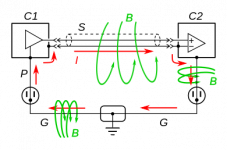
It's Douglas Self's schematic. After that:
Consider, if you will, the points circled in red. These are mechanically different points, but electrically the same point (disregarding conductor resistance).
Making these connections forms the chassis and cable shield (screen) into a continuous shield around the audio circuit and all associated conductors. No gaps, no breaks, a continuous shield, all electrically the same point.
Consider next the circuits that precede and/or follow the shown circuit. Assume (or hope) that these are similarly connected, and therefore similarly shielded.
The result is an unbroken shield around all circuits and all conductors, all electrically the same point.
Now consider the small green triangle. This is the building's grounding system, which really is ground. It's ultimately a ten-foot rod driven into the earth (planet earth) near the building's electric meter.
If you'll imagine this, perhaps you'll see that every audio chassis in a building, and every audio cable shield, is ultimately connected to the same mechanical point--the grounding rod--and that all are electrically the same point (still disregarding conductor resistance).
These are some real-world facts that I thought might be of interest.
(Just to mention it, the building next door has a similar grounding system connected to a grounding rod, and so does the one after that, and the one after that. In fact, all the buildings in the world have a similar grounding rod. This is mandated by all electrical codes, there's an international committee.)
.
Bentsnake I like your up scaling of the problem. What would happen if you measure the voltage between your ground and your neighbours ground, to add a little reality to the problem we will do the measuring up in the attics of each house.
My neighbour wants to install an intercom between the two attics. Because I am not very bright I connect the audio return (shield) that runs between the two attics to each ground.
Groundloop!
At this point anybody who's interested can simply go outside and look around near their meter. You'll see a couple-three inches of the ground rod sticking out of the ground, with a wire going into the house (or some terminal box) clamped on.
Actually no. It is different in different locales.
I've done residential wiring part time for 30 years. The only place you'll see a rod here is in a garage or shop that has its own service or sub panel. Residential wiring service is always grounded to the plumbing via a specific type of bonding clamp.
It's dangerous for you to keep saying this.
Actually it's dangerous for people that aren't absolutely certain what they're talking about to give advice on this topic.
I tell aspiring DIYers to stick to plumbing, because all you're going to get is wet. Horsing around with residential wiring when you aren't absolutely certain of what you're doing is tantamount to playing with lightning. And you can burn your house down.
If anybody should disconnect the bonding wire from the ground rod there's a real danger of electrocution
And you're right about this. Plumbers often mess up the grounding scheme here. Even changing the pipe routing can be dangerous. I see improper grounds all the time. My house wasn't even grounded properly when I bought it because a plumber had replaced a section of pipe and he used some kind of plastic bushings on the connection. 😱 The ground wire was six feet away and obviously grounded through this pipe. But hey, he's a plumber; not an electrician.
The Protective Earth inside the house is connected to the Neutral at the distribution board.
It should be bonded there and there only. Ground and neutral are two different things. Neutral is called the "designated conductor" because it completes the circuit, not the ground.
Bentsnake I like your up scaling of the problem. What would happen if you measure the voltage between your ground and your neighbours ground, to add a little reality to the problem we will do the measuring up in the attics of each house.
I've actually done this, and observed voltage differences up to 15 volts. The reason it was so high is because there was a defective (but still operational) old refrigerator plugged in down in one of the basements.
Try it, and you will almost certainly observe at least a small voltage drop between two residences.
Last edited:
Residential wiring service is always grounded to the plumbing via a specific type of bonding clamp.
This older method has been illegal for years, and in older building it's replaced when electrical repairs are made. This is partly due to the modern use of plastic plumbing pipe. But you obviously can't go back to millions of houses and make the owners rewire them.
.
Last edited:
Ground and neutral are two different things. Neutral is called the "designated conductor" because it completes the circuit, not the ground.
Yep. And grounding is called, correctly, bonding. Different names for different things.
.
What would happen if you measure the voltage between your ground and your neighbours ground...
Was some sarcasm intended there? Surely not.
You're correct, there might well be a voltage difference between different points on mother earth. Just to mention it for fun, this especially applies to islands, due to the conductivity of salt water. People who live in Key West, for instance, are literally living on a battery.
But knowing this, I now have to make a decision about why I'm posting in the first place. Am I trying to help this guy out by giving him useful information that he can understand, or am I trying to show off how smart I think I am? Decisions, decisions.
OK the subject of ground rods is closed, at least for me. Anybody who wants to actually know what they're talking about can Google the subject.
.
Last edited:
I don't do sarcasm.
Ground loop (electricity) - Wikipedia, the free encyclopedia
Helpful link, see "Sources of ground current" and "Solutions".
Ground loop (electricity) - Wikipedia, the free encyclopedia
Helpful link, see "Sources of ground current" and "Solutions".
Attachments
I've been doing residential electrical wiring for decades. I stay abreast of all the new electrical codes.
The codes are different in different locations. I always check with the local building department if I am not sure of something. Bonding to plumbing pipe is still required in many locales, including where I live. Ground rod is required in some locales. Both work equally well if implemented properly. Both can be dangerous if someone that doesn't know what they're doing monkeys with them; and this happens all the time.
Are you calling me a liar, Snake?
Lol this thread sure opened a can of worms.
Anyways I am going to design this with what worked as I mentioned earlier unless someone gives me reason to change that.
This method so far has proven to work flawless and conveniently allows me to bond the input jack to the metal chassis and as mentioned allows the guitar itself to act as part of the amps body and grounded directly to earth for safety.
I find it incredibly interesting how deep grounding issues can go with audio amplifiers. There is a whole field of study with grounding alone it seems lol.
Who would have thought something that should in theory be simple would result in so many opinions and variations?
There is a whole field of study with grounding alone it seems lol.
Actually that's true. An example by the founder:
http://www.amazon.com/Grounding-Shielding-Interference-Ralph-Morrison/dp/0470097728
This is something I'm going to have to ask about, because it is often stated, but is not a statement that makes sense, without some amount of never-stated context.Before anything else, the #1 rule that everybody agrees on is keeping the audio signal away from the relatively large power supply voltages and currents. Obviously this is done to avoid distortion of the audio signal. Not so obvious is that this rule applies as much to the return side as the hot side.
The "audio separate from power" rule applies to the return side because: a) ICs (integrated circuits) work on very low voltages and currents, and: b) these voltages and currents are so low that the real-world resistance of straight wires becomes a factor. A straight wire has only milli- or micro- ohms of resistance, but with ICs milli- and micro- volts and amps are involved, so E=IR becomes significant.
Power voltages and currents must use the same common, making it impossible to at all separate the signal from power. Likewise, power, signal, and commons all come together in at least one component, if not several. If there is a large current going through the power supply rails, it's going through a component handling the signal, and then usually (with SE, always) going to the same common. If the given diagrams are, "audio separate from power," what does, "audio with power," look like? Given the requirements of powering the circuitry, and where current must flow, the definition of, "separate," is not the same one from the dictionary, whatever it may be.
Power voltages and currents must use the same common, making it impossible to at all separate the signal from power.
Likewise, power, signal, and commons all come together in at least one component, if not several.
Large current pulses flow through some conductors in the power supply due to diode rectification, and coupling to the audio circuit causes noise.
This coupling can be caused by an Ohmic audio circuit connection to a noisy point in the power supply, or by inductive coupling due to proximity.
More subtle problems include, for example, minimizing loop area in audio circuit paths (which often include some power supply components).
Problems like these can be minimized (or prevented) by good design.
Last edited:
If the given diagrams are, "audio separate from power," what does, "audio with power," look like?
C'mon. Keep audio signal conductors away from power supply conductors.
That is, until you come to circuit ground. At which point you bow politely to the laws of physics and hook 'em up.
Still, if you like you can give a moment's consideration to the unsung hero of our drama, the transformer.
Compared to any other part of the circuit the transformer is a mountain of voltage, and a tsunami of current. It simply sweeps all before it. So at circuit ground, which is a transformer terminal, all differing voltages and currents are swamped--actually an engineering term--by the transformer itself. They simply disappear into the maelstrom. To be strictly accurate they're still there, but compared to the transformer's voltage and current they become insignificant. Then the job is touched up by the capacitor bank, and in essence the circuit is reset.
But much beyond this things quickly become mathematically terrifying. I counsel sticking to the KISS rule, and try not to think too much.
.
- Status
- Not open for further replies.
- Home
- Amplifiers
- Chip Amps
- Confused over various grounding methods and designs