Sorry if this is not the right place but the guitar amplifier I am designing around the LM3875 chip has me scratching my head over what to do for the overall grounding scheme.
There is a sensitive preamp circuit I designed which includes a clean/fuzz channel switch, so even the smallest error in grounding inputs, outputs, pots, main grounds and so on can mean the difference between a tame amplifier and one that squeals from ground loops.
It is my understanding that the idea is to not have more than one ground path to a circuit. As in the input jack, speaker jack, headphone, and chassis should all be separated in that they all receive their own ground connection to the overall star ground.
This is really bugging me how the smallest change in ground is making a night and day difference in this design.
So here is my plan, and please tell me if I have something wrong here...
-Input jack and speaker jack and headphone jacks all have their ground separated from each other at the jack (no connection to faceplate metal) and each goes to their respective ground on the circuit board via shielded cables.
-Main amplifier board has everything star grounded just like any other chipamp, then rectified filtered DC running to to that and the positive connections.
-Preamp circuitry all having its own star ground, that then connects to the main amps star ground on the circuit board.
-Finally.. metal chassis itself connected to the ground on AC outlet, and a resistor/capacitor from chassis to the main amplifiers star ground.
Do I have this all correct?
This is quite confusing to me because I am use to RF electronics where everything is a matter of RF shielding on the same ground, or even antique electronics where all jacks and controls and chassis were grounded to each other directly, even sometimes with multiple grounds going to the same thing (example: volume pot grounded to chassis, shielded cable going to volume pot with ground also wired to chassis, aka: two ground paths).
So as I understand it the rules are... No multiple ground paths to the same part either through wires or chassis.
There are three separate grounds, chassis, circuits, and input jacks, that all eventually connect together at one point.
Sorry for the long post.
It is one thing to design an amplifier with line inputs only, but when you add a sensitive preamplifier and tone circuitry in the same unit, things get complex!
PS: If anyone knows some good tutorials or documents I can read through about this subject please link me. Sorry if this is a common question.
One more quick question.. Am I correct in assuming this all as modern electronics always separate the RCA and 1/4 plug inputs from the chassis body if metal using plastic jacks and plastic nuts to hold them in place, whereas old electronics often had their input/output jacks with metal ground threading touching metal chassis?
What changed since times past?
What changed since times past?
Number ONE in my book (don't worry, you're safe from me! I will never become an author),
is give EVERY CIRCUIT it's necessary FLOW and RETURN connection/s to the outside world.
Then you will find that all your confusing "grounds" have gone away to bother those other Members who continue to use this most confusing of words in our DIY dictionary.
Once you have EVERY Flow and Return identified, make sure this pair are close coupled along the whole route from module to module.
Then, as an extra belt and braces, try to twist every close coupled Flow and Return.
This practice minimises the interference effects of aerials in our systems. The receiving aerials and the transmitting aerials become very ineffective when the two conductors are twisted pairs.
It is all about LOW LOOP AREAS.
In an amplifier one often finds that the separate modules need a common reference. This applies to opamps and Power Amps. The input and the output NEED a common reference. I like to call this the "Main Audio Ground" (MAG), because it does not get confused with all the other Members' misused "ground" word.
Last edited:
.
You'd probably expect that power supplies and grounding would be mature technology, with all issues long since settled. But this is partly true, and mostly not. There are gray areas where judgment enters in, and this very much includes the subject of grounding.
Before anything else, the #1 rule that everybody agrees on is keeping the audio signal away from the relatively large power supply voltages and currents. Obviously this is done to avoid distortion of the audio signal. Not so obvious is that this rule applies as much to the return side as the hot side.
The "audio separate from power" rule applies to the return side because: a) ICs (integrated circuits) work on very low voltages and currents, and: b) these voltages and currents are so low that the real-world resistance of straight wires becomes a factor. A straight wire has only milli- or micro- ohms of resistance, but with ICs milli- and micro- volts and amps are involved, so E=IR becomes significant.
Posted below is a succession of images, intended to progress from the basic principle to real-world application.
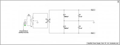
Figure 1 is simply the usual schematic for a power supply. You're supposed to look at it and admire the simplicity of the concept.
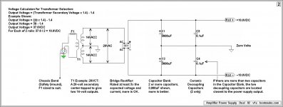
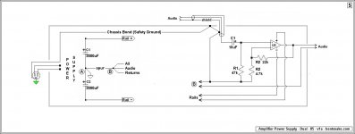
Figure 2 is the same (literally) schematic, but with notes added that I hope are self-explanatory.
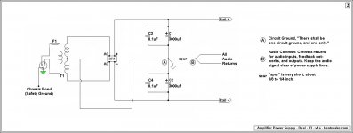
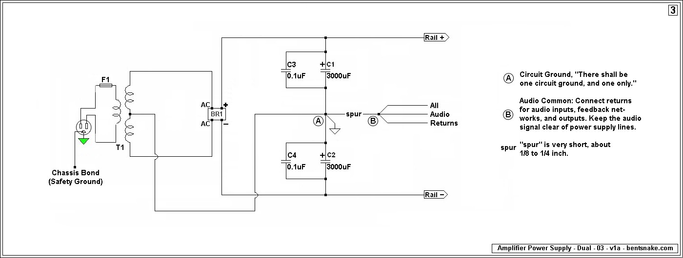
Figure 3 is electrically identical to the first two, but mechanically different because real-world wiring connections are shown.
Figure 5 brings everything together--I hope--showing how the audio circuit connects to the power supply.
I'm not making this stuff up. All of this is as suggested by audio gurus of serious reputation, including the chip manufacturers themselves. However, I don't present any of this as "the way you do it." As before, in the gray areas there's room for judgment, so you pretty much pays yo'money and takes yo' choice.
I should add that what I'm presenting here is the Cadillac way of doing things. In contrast, when building just a small preamp, stompbox, or similar, it's not uncommon to just hook all the grounds/commons/returns together in the way that's most convenient. This is the "ground bus" method, and it's likely to work just fine. However, following the "audio separate from power" rule is always a wise.
.
You'd probably expect that power supplies and grounding would be mature technology, with all issues long since settled. But this is partly true, and mostly not. There are gray areas where judgment enters in, and this very much includes the subject of grounding.
Before anything else, the #1 rule that everybody agrees on is keeping the audio signal away from the relatively large power supply voltages and currents. Obviously this is done to avoid distortion of the audio signal. Not so obvious is that this rule applies as much to the return side as the hot side.
The "audio separate from power" rule applies to the return side because: a) ICs (integrated circuits) work on very low voltages and currents, and: b) these voltages and currents are so low that the real-world resistance of straight wires becomes a factor. A straight wire has only milli- or micro- ohms of resistance, but with ICs milli- and micro- volts and amps are involved, so E=IR becomes significant.
Posted below is a succession of images, intended to progress from the basic principle to real-world application.
Figure 1 is simply the usual schematic for a power supply. You're supposed to look at it and admire the simplicity of the concept.
Figure 2 is the same (literally) schematic, but with notes added that I hope are self-explanatory.
Figure 3 is electrically identical to the first two, but mechanically different because real-world wiring connections are shown.
Figure 3 is where the various this-grounds and that-grounds come in. All these different "grounds" seem to--and do--violate the rule of "one ground point, and one only." I resolve this conflict by referring to everything except the shown Point A as "commons."
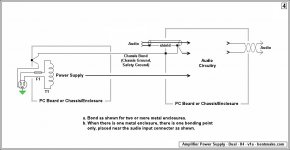
Figure 4 shows the chassis bond. This is also called chassis ground, safety ground, and probably a dozen other names.
Figure 5 brings everything together--I hope--showing how the audio circuit connects to the power supply.
I'm not making this stuff up. All of this is as suggested by audio gurus of serious reputation, including the chip manufacturers themselves. However, I don't present any of this as "the way you do it." As before, in the gray areas there's room for judgment, so you pretty much pays yo'money and takes yo' choice.
I should add that what I'm presenting here is the Cadillac way of doing things. In contrast, when building just a small preamp, stompbox, or similar, it's not uncommon to just hook all the grounds/commons/returns together in the way that's most convenient. This is the "ground bus" method, and it's likely to work just fine. However, following the "audio separate from power" rule is always a wise.
.
Attachments
Last edited:
One more quick question.. Am I correct in assuming this all as modern electronics always separate the RCA and 1/4 plug inputs from the chassis body if metal using plastic jacks and plastic nuts to hold them in place, whereas old electronics often had their input/output jacks with metal ground threading touching metal chassis?
What changed since times past?
Nooo! Some jacks/connectors might be internally bonded [to ground], others might not be. You have to examine the specs. Often this means clicking through to the manufacturer's spec sheet (sometimes given, sometimes not) and studying that.
Usually a non-bonded jack/connector will be called "insulated," but you can't depend on that one way or the other unless it's clearly stated what "insulated" means.
.
There is a sensitive preamp circuit I designed which includes a clean/fuzz channel switch, so even the smallest error in grounding inputs, outputs, pots, main grounds and so on can mean the difference between a tame amplifier and one that squeals from ground loops.
Ground loops commonly produce hum, squeals are feedback. Do your circuits include decoupling and/or bypass capacitors?
If your answer is "I don't know," then they probably don't. But you'd have to post a schematic for there to be any useful discussion.
However, if you're not already following the rule of "audio separate from ground," then that might be the solution to more than one problem.
.
This is quite confusing to me because I am use to RF electronics where everything is a matter of RF shielding on the same ground, or even antique electronics where all jacks and controls and chassis were grounded to each other directly, even sometimes with multiple grounds going to the same thing (example: volume pot grounded to chassis, shielded cable going to volume pot with ground also wired to chassis, aka: two ground paths).
Then these are tube/valve circuits? Don't confuse yourself by directly comparing tubes/valves to ICs. The hundreds of volts that tubes/valves work on are a whole different world.
Also, antique devices had no third (bonding) conductor on the wall plug. More opportunity for confusion.
.
...metal chassis itself connected to the ground on AC outlet, and a resistor/capacitor from chassis to the main amplifiers star ground
The "ground lift" method goes by various names. Some swear by it, others, such as me, consider it a sloppy workaround that might be illegal where you live, and dangerous to boot.
Call it whatever, ground lift introduces an unknown by un-bonding the chassis. This can mean that you have everything else right, but the ground lift itself is causing hum.
I suggest that you remove the ground lift for troubleshooting purposes, instead bonding the third conductor of the wall receptacle directly to the chassis, which really is a bond. Then if all else fails again resort to a ground lift.
Ummm...you have tried plugging everything into the same wall receptacle? Using a power strip if necessary, or much better, just a plain ol' multi-outlet extension cord?
.
Possibly a Root Cause
Reading along in your post, this finally jumps out at me. Possibly your problem in the first place (or possibly not).
I'm not certain of what you mean by "preamp star ground" and "main amp star ground," but if I'm thinking right I can see these being connected together as fatal. The small audio signals in the preamp fall victim to the larger currents and voltages in the main amp, and everything gets scrood.
Solution: referring to my own post #4.
Assuming that I'm picturing correctly what you're doing, the preamp star ground instead runs directly to what I call Point A, circuit ground at the power supply, and the main amp star ground does the same.
Of course, always keeping audio signals away from power supply lines.
OK last post, I'm giving somebody else a chance.
.
Preamp circuitry all having its own star ground, that then connects to the main amps star ground on the circuit board.
Reading along in your post, this finally jumps out at me. Possibly your problem in the first place (or possibly not).
I'm not certain of what you mean by "preamp star ground" and "main amp star ground," but if I'm thinking right I can see these being connected together as fatal. The small audio signals in the preamp fall victim to the larger currents and voltages in the main amp, and everything gets scrood.
Solution: referring to my own post #4.
Assuming that I'm picturing correctly what you're doing, the preamp star ground instead runs directly to what I call Point A, circuit ground at the power supply, and the main amp star ground does the same.
Of course, always keeping audio signals away from power supply lines.
OK last post, I'm giving somebody else a chance.
.
Last edited:
Correction to Post #6
.
My post #6 says, "...if you're not already following the rule of 'audio separate from ground,' then that might be the solution to more than one problem.
Of course this should be, "...if you're not already following the rule of 'audio separate from power supply,' then that might be the solution to more than one problem.
It's kind of inconvenient that posts can't be edited.
.
.
My post #6 says, "...if you're not already following the rule of 'audio separate from ground,' then that might be the solution to more than one problem.
Of course this should be, "...if you're not already following the rule of 'audio separate from power supply,' then that might be the solution to more than one problem.
It's kind of inconvenient that posts can't be edited.
.
Just to clear up some confusion, the project is still laying on my workbench and I haven't even got to the point of building the chassis yet. I am just accumulating some information before I get that far along.
This is just a personal project for myself as a hobby. The circuitry is all my design besides the chipamp section which I basically copied the design that is in the texas instruments documentation.
By squealing I should have mentioned that it is mostly related to the grounding of the preamp circuitry, the tone/volume controls ground, and so on.
Everything behaves on the bench as is right now, but I want to make sure that when grounding is designed into the chassis and all the pieces come together that it will remain that way.
Being as it is a guitar amplifier the input is very sensitive. Add in the fuzz distortion circuit and it becomes sensitive to just about any variation in layout and where things are grounded when it comes to hum and potential feedback.
Anyways thanks for all the information so far.
I hope the focus is more on my initial questions regarding grounding in general rather than my project as is right now since it is still in the design phase.
Sounds more like a Preamp and too much gain issue.
Did you add in capacitance in parallel with Rf resistors in your gain stages (Compensation)?
Sometimes this can help with the squealing as it limits the high frequency gain.
I have a Park practice amp, and it has this problem as well since it has so much gain.
A JFET front end an opamp and a TDA2030 is in it, I just haven't had the time to go through and try to solve it since i do like the way it sounds stock when it is not squealing.
Back in the day when I used to build my own high gain stages I also had severe problems with Microphonic Feedback from the pickups on my Strat.
I had to dip them in wax to solve this and all was good after that, except for the Lead pickup!
You have to be very careful when dipping them as the wire is so fine that somehow it got broke with an open winding and killed the pickup.
I had read about the possibility of this happening, but I never thought that it would happen to me being as extremely careful I was, But it happened.
So that was a $110 mistake to replace it!!!
Although I did get a nicer Seymour Duncan SDS that had just come out at the time and then life was Good Again......Very Good !!
Once you get everything mounted in a case the problem just might go away!
You would be very surprised to find how important it is sometimes for circuits to be sealed in an metal enclosure of some sort.
Through the years I have had many projects fail only because I never took the time to put them in a proper case. 😉
FWIW
jer 🙂
This (un-bonding) must NEVER be implemented.................ground lift introduces an unknown by un-bonding the chassis. ...............
The Chassis MUST be directly bonded/bolted to the Protective Earth wire in the mains supply cable.
There are no safe exceptions for our builds.
Bent,
stop sending out confusing and potentially fatal post advice, that may get read by any Members, including beginners.
This (un-bonding) must NEVER be implemented.
The Chassis MUST be directly bonded/bolted to the Protective Earth wire in the mains supply cable.
There are no safe exceptions for our builds.
Bent,
stop sending out confusing and potentially fatal post advice, that may get read by any Members, including beginners.
Your out-of-context quote is deceiving, and you're confused. Please read more carefully.
.
Last edited:
I should connect ground between A and B, not at A.
There are current pulses where A is currently located.
If I ever used C3 and C4, 100 nF, I would never connect them across electrolytics C1 and C2
Since some years, I use non-isolated RCA sockets.
This can give a general layout much more in accordance with the ground equipotentiality concept (trying to maintain the lowest impedance in the ground path everywhere) than what is obtained when applying the "rule" of star grounding (which is only a "recipe" for me).
Last edited:
I and others have told Bent this already and he continues to post these erroneous bits of advice.I should connect ground between A and B, not at A.
There are current pulses where A is currently located.
If I ever used C3 and C4, 100 nF, I would never connect them across electrolytics C1 and C2
..............
I should connect ground between A and B, not at A.
There are current pulses where A is currently located.
If I ever used C3 and C4, 100 nF, I would never connect them across electrolytics C1 and C2
Since some years, I use non-isolated RCA sockets.
This can give a general layout much more in accordance with the ground equipotentiality concept (trying to maintain the lowest impedance in the ground path everywhere) than what is obtained when applying the "rule" of star grounding (which is only a "recipe" for me).
I wonder whether you're offering your method as an alternative to mine, or insisting that yours is the only correct method of grounding?
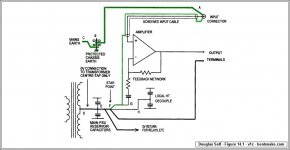
In either case you might not know that this is an old discussion, apparently not likely to ever be settled. But as I said in post #4, I'm not making any of this up. The grounding method I offer is based heavily on one recommended by Douglas Self (with others). I post Mr. Self's method for the 10,000th time around here, on the off chance that somebody might look at it this time.
.
I and others have told Bent this already and he continues to post these erroneous bits of advice.
In contrast, AndrewT knows all about this ongoing discussion. He also knows about Douglas Self's method, and about some half-dozen other recognized authorities I've referenced, including manufacturers' sites.
None of which seems to register. Instead, as we see here, he presses for acceptance of his own ideas by mocking those offered by others. When someone asks for an explanation of his ideas he announces, "I have already explained that," without ever saying where the explanation can be found.
Again quoting myself from post #4, "There are gray areas where judgment enters in, and this very much includes the subject of grounding." This appears to me to be a fact. But if others decide that they alone are the source of understanding, their judgment reigning supreme over that of all others, well then, they do.
Except apparently now we have to wait to see what forr and AndrewT decide between themselves. I, for one, am on tenterhooks.
.
A very strong +1 to AndrewT comment above.
Run, do not walk, to the nearest dictionary and look up "sycophant."
.
Attachments
Last edited:
Wow, go for the knees! Sorry, but he's correct. I've been on here for some years and there are several posts and discussions on the topic. Some I've even searched out and read myself and discussed with others. It's all in there.
Sorry, I have two little ones so I go the safest route on my projects. That's the way I roll and this has been discussed ad nauseaum and it's pretty easy if you just search under 'ad nauseaum'. LOL
Sorry, I have two little ones so I go the safest route on my projects. That's the way I roll and this has been discussed ad nauseaum and it's pretty easy if you just search under 'ad nauseaum'. LOL
.
Even so, one can try to have a rational discussion without ultimatums and name calling.
<< I should connect ground between A and B, not at A. >>
Then what, if anything, would you connect to point A? If you don't connect anything, then the new connection just becomes a new point A, and everything remains the same.
<< If I ever used C3 and C4, 100 nF, I would never connect them across electrolytics C1 and C2 >>
But instead you'd...? It would be ever so much more helpful if you'd say how you would connect them.
.
Even so, one can try to have a rational discussion without ultimatums and name calling.
I should connect ground between A and B, not at A.
There are current pulses where A is currently located.
If I ever used C3 and C4, 100 nF, I would never connect them across electrolytics C1 and C2
<< I should connect ground between A and B, not at A. >>
Then what, if anything, would you connect to point A? If you don't connect anything, then the new connection just becomes a new point A, and everything remains the same.
<< If I ever used C3 and C4, 100 nF, I would never connect them across electrolytics C1 and C2 >>
But instead you'd...? It would be ever so much more helpful if you'd say how you would connect them.
.
- Status
- Not open for further replies.
- Home
- Amplifiers
- Chip Amps
- Confused over various grounding methods and designs