think you know very well what I'm talking about. Most diy'ers shoot for a response like this:
An externally hosted image should be here but it was not working when we last tested it.
...and here's the response of Danley's TH812, which looks even smoother than that. So I'm not seeing the point you're trying to make with your sweeping generalization about his THs.
Attachments

I'd say I've confirmed HornResp can approximate cone compensation...
Sure, but this was never in question. Accurate sims match measurements. I've been saying this for years.
...and here's the response of Danley's TH812, which looks even smoother than that. So I'm not seeing the point you're trying to make with your sweeping generalization about his THs.
Yeah, it says right on it 10 percent smoothing, it's a wide and short graph (very unlike Hornresp's tall and narrow graph) with 10 db between the lines (crunched down to look smooth) and it may have stuffing in it too. Sim the cab and it won't look nearly that smooth.
IN GENERAL DSL's cabs are bigger, have lower compression ratio than MOST diy'er sims and builds. The DSL cabs I've simulated have been wildly undamped, and even with stuffing are fairly undamped, like the TH_SPUD.
Last edited:
That's severely overdamped compared to DSL's tapped horns, no bump at Fb, no bump before the big spike, no undamped bumps anywhere really (except the problematic tapped horn spikes that are very hard to get rid of), because it's overdamped. Very high compression ratio and small horn = response as shown there, the small size and flat(ish) response are very appealing to many diy'ers and MOST sims I've seen are more like this one than DSL's.
I just wanted to touch on this again this morning.
That DSL's alignments differ from a DIYer's alignment could also simply mean that different design goals are being considered, and not that any of them is "right" or "wrong". The DIYer might be shooting for a flat response and extended low frequency response and DSL might be shooting for better in-band power handling and smaller box size, for example. There's also the issue of HornResp and box losses - it has been suggested that shooting for a slightly underdamped alignment in HornResp will produce a flatter response for the build, as HornResp does not take box losses into consideration.
I will say though that, for TH alignments that feature a deep notch at the upper end of the passband, it seems those designs appear to eliminate one of the purposes of using a TH alignment in the first place.
Sim V Real
Another difference, is where the Real are/were measured, & under what conditions etc.
Another difference, is where the Real are/were measured, & under what conditions etc.
Hi Brian,
thanks for taking this on. How much trouble can I cause!
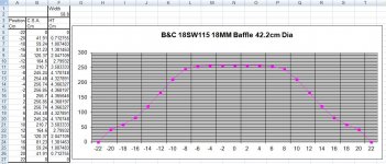
When developing this concept, I modelled a speaker cone volume in 3D CAD and added the volume of the baffle cut out. I then took incremental cross sections of this volume to find the cross sectional area at differing points along the speaker path.
The data was entered into a spreadsheet. It was immediately apparent that over the centre section of the speaker that this cross sectional area does not vary by much - the curve has a virtually flat bottom.
The cross sectional areas were then divided by the internal width of the speaker to derive the final heights for the 'Cone Correction'
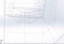
This cone correction curve is finally simplified and plotted along the line of the speaker baffle edge. The cone correction curve is then assumed to be the line of the speaker throat path, replacing the inner edge of the speaker mounting baffle.
The internal baffle is then modified to accommodate the cone correction curve taking account of the required horn shape. As such there is no attempt made to mimic the shape of the speaker cone, but just to account for the varying cross sectional area along the speaker path.
The results you posted are promising - especially as you are suggesting an increased output with 3 litres less volume.
Integrating the shaped inner baffle into a new build with the SS15 - TH18 - POC #3 type fold can increase the path length as well.
Hope this helps
Regards Martin
thanks for taking this on. How much trouble can I cause!
When developing this concept, I modelled a speaker cone volume in 3D CAD and added the volume of the baffle cut out. I then took incremental cross sections of this volume to find the cross sectional area at differing points along the speaker path.
The data was entered into a spreadsheet. It was immediately apparent that over the centre section of the speaker that this cross sectional area does not vary by much - the curve has a virtually flat bottom.
The cross sectional areas were then divided by the internal width of the speaker to derive the final heights for the 'Cone Correction'
This cone correction curve is finally simplified and plotted along the line of the speaker baffle edge. The cone correction curve is then assumed to be the line of the speaker throat path, replacing the inner edge of the speaker mounting baffle.
The internal baffle is then modified to accommodate the cone correction curve taking account of the required horn shape. As such there is no attempt made to mimic the shape of the speaker cone, but just to account for the varying cross sectional area along the speaker path.
The results you posted are promising - especially as you are suggesting an increased output with 3 litres less volume.
Integrating the shaped inner baffle into a new build with the SS15 - TH18 - POC #3 type fold can increase the path length as well.
Hope this helps
Regards Martin
Attachments
Consider various sizes of Styrofoam blocks or wooden disks to take up delta Vtc volume theory to approx. compression, I wonder about your choice of wedge or other aerodynamics shapes may skew results.
Last edited:
Consider various sizes of Styrofoam blocks or wooden disks to take up volume , I wonder about your choice of wedge or other aerodynamics shapes may skew results.
I think for the wavelengths being considered, the impact of the shape of the compensation on the FR will be minor. Once the objects in question are smaller than 1/4 of the wavelengths being considered, their shape is likely to be non-issue. At 200 Hz, 1/4 wavelength is over 41 cm (16 in.).
Integrating the shaped inner baffle into a new build with the SS15 - TH18 - POC #3 type fold can increase the path length as well.
Yep, that was the idea - basically kill two birds with one stone.
The layout of the TH115/8 suggests however that there's a lot more than "cone compensation" going on. The amount of "compensation" seems to be 2 to 3 times the amount actually required. This suggests that there's another purpose to it.
I tried to include cone compensation in my POC4 design, splitting that section of the horn into two, rather than three parts as in the TH115 and TH118. I ended up with good results, but went around the wrong way of doing it, LOL. I just looked at the CSA through the center of the driver and decreased the CSA @ S2 to compensate. What I should have really looked at was the volume of air in the cone and decreased the volume across S2 accordingly. Oh well, I'll adjust the design spreadsheet accordingly to look at the volume and use that to calculate the corresponding change in CSA @ S2.
Attachments

@ Brian Steele
Your Post # 49 screenie is more like what i was hinting at earlier. Compensating for the debatable Actual start of the CSA !
Your Post # 49 screenie is more like what i was hinting at earlier. Compensating for the debatable Actual start of the CSA !
The layout of the TH115/8 suggests however that there's a lot more than "cone compensation" going on. The amount of "compensation" seems to be 2 to 3 times the amount actually required. This suggests that there's another purpose to it.
To illustrate this, see diagram below, where I've compared what's known about the TH115's layout to a TH with no "cone compensation". The yellow section is where the volume @S2 has been decreased. There's also a small *increase* in volume @S1, which I suspect is was just done to avoid having to add an additional panel.
I estimate the decrease @ S2 at around 12 liters, which is over double what I'd expect if it was just for "cone compensation" for a 15" driver. And I don't believe it can be emulated in HornResp, as HornResp does not allow you to "pinch" the horn like that in a sim. If you try to decrease S2 in HornResp in an attempt to emulate the pinch, you'll affect the expansion of the horn all the way up to S3, which significantly changes its layout.
Attachments
Again, my suggestion is that "cone compensation" was not even on his mind when he drew this up. There are SIGNIFICANT benefits to this layout, it allows for a LOT more path length in the same box volume, so with clear advantages that have nothing to do with "cone correction" there's no need to jump to the assumption that "cone correction" was a factor in this layout at all. And again, there's no "cone correction" in any of his other designs, so assuming that he consciously intended to do it in this design is a bit of a leap.
Sure, Hornresp can do this just fine. Shove the driver all the way right so S1 is at the edge of the driver, then S2 is at the middle of the driver and put S3 right at the end of the driver. That uses up most of your segments in the first few inches of the horn, but Hornresp can do it.
If you need more segments export to Akabak and continue. It's a pain but it isn't difficult and unfortunately I have to do it quite a bit to get high degrees of accuracy in sims.
And I don't believe it can be emulated in HornResp, as HornResp does not allow you to "pinch" the horn like that in a sim. If you try to decrease S2 in HornResp in an attempt to emulate the pinch, you'll affect the expansion of the horn all the way up to S3, which significantly changes its layout.
Sure, Hornresp can do this just fine. Shove the driver all the way right so S1 is at the edge of the driver, then S2 is at the middle of the driver and put S3 right at the end of the driver. That uses up most of your segments in the first few inches of the horn, but Hornresp can do it.
If you need more segments export to Akabak and continue. It's a pain but it isn't difficult and unfortunately I have to do it quite a bit to get high degrees of accuracy in sims.
Sure, Hornresp can do this just fine. Shove the driver all the way right so S1 is at the edge of the driver, then S2 is at the middle of the driver and put S3 right at the end of the driver. That uses up most of your segments in the first few inches of the horn, but Hornresp can do it.
If you do it that way, it looks like there's a change in expansion between S3 and S4 in the TH115 that won't be reflected in the sim. Have another look at the layout in the diagram.
Like I said, if you need more segments use Akabak.
My point was that Hornresp can simulate this type of thing, not that it can sim all horns with this type of thing in them. As always, MOST horns need way more segments than Hornresp can provide if you want to be really accurate.
In the case of this horn in particular, it would be good to use a few more segments to reflect the basket blockage and the grill, both those things are going to provide significant changes to response. And if you want to get really accurate and do accurate advanced centerline sim you need a couple dozen more segments. That's why I didn't want to sim this thing in the first place. An accurate sim takes time, quick sloppy sims don't match measurements.
Last edited:
My point was that Hornresp can simulate this type of thing, not that it can sim all horns with this type of thing in them.
..and my point was that HornResp cannot be used to sim something like the TH115, or any horn in fact that has more than one expansion taking place between S2 and S4. Which basically covers *all* the THs discussed in this thread so far - the TH115, the TH118, my POC3, my POC4 and Martin's TH. If it could be used for other THs, great. But it doesn't help here.
I get that. I was countering a very specific statement -
And I don't believe it can be emulated in HornResp, as HornResp does not allow you to "pinch" the horn like that in a sim.
Yes, Hornresp can do that, but it leaves you with a very limited amount of segments for the rest of the horn. It can't accurately sim the horn you want to sim, no argument there. But that particular statement that I was responding to is not true.
I can help you if you want, start the sim in Hornresp, go as far as you can in Hornresp, send me the file with all the details that need to be completed, and I can finish it in Akabak. Depending on how complex you want to get it could take me awhile to find time though. Or you can just do it in Akabak yourself.
In the case of this horn in particular, it would be good to use a few more segments to reflect the basket blockage and the grill, both those things are going to provide significant changes to response.
It would be of academic interest to include that, but I think that's really at the point of diminishing returns. I don't think the basket blockage is going to affect the response that much if the mouth of the horn is sized properly. I used to worry about it before, but I'm not seeing anything in my measurements that suggests the basket is causing a response aberration that can't be explained by other means, so I consider it a non-issue.
As for the grill, if it's noticeably affecting the response of the subwoofer, then perhaps that particular type of grill is not the best solution - who would want to decrease a subwoofer's performance via a grill?
It would be of academic interest to include that, but I think that's really at the point of diminishing returns. I don't think the basket blockage is going to affect the response that much if the mouth of the horn is sized properly. I used to worry about it before, but I'm not seeing anything in my measurements that suggests the basket is causing a response aberration that can't be explained by other means, so I consider it a non-issue.
In the 115 it's not so big a deal, it is still a restriction but the driver isn't huge, in the 118 it's a serious restriction at that point in the line. If you want to be accurate you need to include everything you can.
As for the grill, if it's noticeably affecting the response of the subwoofer, then perhaps that particular type of grill is not the best solution - who would want to decrease a subwoofer's performance via a grill?
A relatively "open" grill is still about 50 percent blocked off, and the blocks of wood all the way around the edge are 100 percent blockage. If you add all this up, the blocks of wood, the grill blockage, the big driver in the 118, you have a very significant amount of blockage.
This considerable blockage does not "decrease a subwoofer's performance", it just changes the csa in those areas. I'd be pretty surprised if the designer did not consider these things as he was designing the horn, he knows what he's doing, and knew before he started that these blockages were going to be present. Even if these things are not considered during the design process, it's just going to tune the design a couple hz lower than expected. But if the point is to do an accurate sim you absolutely do have to account for these things.
Last edited:
The Danley TH118 throat design is fairly radical. Failure to implement it properly with enough clearance or not using a robust enough driver will inevitably cause a failure.
Once the Danley throat shape in the TH115/8 was known, it was obvious that the volume of the speaker cone had to be incorporated into the horn throat. The cone correction method of plotting the throat of the horn allows the Danley TH118 to be simmed in Akabak. I don't know any other method that could be used. As such the cone correction method was partially inspired by the Danley TH118 throat shape.
For the DIY builder the cone correction method hopefully gives a realistic representation of the S2 compression ratio and what is happening in the throat area of any horn with an offset type driver.
Many techniques have been used to restrict the throats of various horn speakers with varying amounts of success. This is the best method I have come up with so far.
The cone correction method of plotting the throat of the horn allows the Danley TH118 to be simmed in Akabak. I don't know any other method that could be used.
You can sim this horn the same as any other horn, just break it into segments and correctly specify lengths and cross sectional areas. "Cone correction" has nothing to do with anything. This particular horn has a unique layout but I'm not sure why everyone seems to insist on calling it "cone correction".
Many techniques have been used to restrict the throats of various horn speakers with varying amounts of success. This is the best method I have come up with so far.
Many people have drawn pictures with various restrictions, but has anyone built and measured anything?
I know of one case where one guy built one thing and subjectively preferred it. I haven't seen ANY measurements of anything yet except in this thread.
Best method in what way? What advantage did this best method achieve? Was anything built and measured to confirm this best method did anything?
- Status
- Not open for further replies.
- Home
- Loudspeakers
- Subwoofers
- "cone compensation" - a test case