testing buf634t
Hi there,
I'm trying to building a headphone amp with more or less the same schematics here. I set the gain to be 10. I blew a pair of ear-plug head phones first time I connected the amp. There was nothing wrong withe the circuit. Then I check the dc offset. Far to high. Then I suspected BUF634T to be dodgy. I isolated the buffer, connected +/- 17v and got 10v offset at pin 4 without any input. I put a dummy load of 32R 2W (headphone impedience) across pin 4 and got 0.06A. I then tested the whole batch of buf634s I have. Some result. Can someone tell me if I'm lucky enough to get a bunch of bad eggs or these are the readings you're supposed to get.
Cheers,
KK
Off topic for this thread, but ...
Make sure the input to the BUF634 is at 0V. Something is wrong with your circuit, and there are only 4 pins to the BUF, so it shouldn't be too hard to figure it out.
As to the input cap, I'd say leave room for a small sized one. I usually end up going offboard with input caps anyway because the good ones are so large.
Hi,
First, on the subject. I wound leave a space of 7.5mm pitch on board. One can fit a polyester cap on it or that lead for bigger polyprop. ones.
I'm sorry for the "off" topic question again. Thank you Paulb for the hint. There was no circuit when I test the buf634t - all connections straight to the chip - two voltage and one output, that's all. So, what should be the proper offset and current one gets in this case. I thought this question might be vaguely related to this thread for one has to test the bufs somehow.
Cheers,
KK
kkchunghk said:Hi,
First, on the subject. I wound leave a space of 7.5mm pitch on board. One can fit a polyester cap on it or that lead for bigger polyprop. ones.
I'm sorry for the "off" topic question again. Thank you Paulb for the hint. There was no circuit when I test the buf634t - all connections straight to the chip - two voltage and one output, that's all. So, what should be the proper offset and current one gets in this case. I thought this question might be vaguely related to this thread for one has to test the bufs somehow.
Cheers,
KK
KK you can't leave the input on the buffer floating. For testing purposes you should have it referenced to half the supply voltage, or GND if using dual supplies. You describe the input pin as unconnected, that will only lead to disaster. 🙂
Cheers
How do you want to handle the signup for the boards?
E-mail or Wiki or something else?
I must say that these boards came in just the right time, I was looking for stuff to add to my "old" gainclone (old means approx 6 months 😀 ).
E-mail or Wiki or something else?
I must say that these boards came in just the right time, I was looking for stuff to add to my "old" gainclone (old means approx 6 months 😀 ).
Hi Russ
Is there any way this group buy can happen at the same time as the Rev C GB ? Could you guesstimate the cost of a parts kit for a freebird and PS ? Including OPA and boards ? How much for Yardbirds w/kit ?
Does a Mauro Rev C have to have a preamp ?
Is there any way this group buy can happen at the same time as the Rev C GB ? Could you guesstimate the cost of a parts kit for a freebird and PS ? Including OPA and boards ? How much for Yardbirds w/kit ?
Does a Mauro Rev C have to have a preamp ?
squalor said:Hi Russ
Is there any way this group buy can happen at the same time as the Rev C GB ? Could you guesstimate the cost of a parts kit for a freebird and PS ? Including OPA and boards ? How much for Yardbirds w/kit ?
Does a Mauro Rev C have to have a preamp ?
Hi,
It is possible, I will likely try to order some FB and YB PCBs at the same time I order the REV C monoblocs(probably in 3 or 4 weeks). I am currently on vacation, but when I get back next week I will start pricing out kits fully. Keep in mind the opa627 and buf634 are the most expensive pieces, but I will see if I can get a quantity discount.
I would imagine( a complete guess) about $45 for a complete freebird kit minus the trafo, I could check on including a small toroid as well. 🙂
Maybe it would be good for those interested in kits to let me know what they would like in a kit. 🙂
Cheers
Russ
To get this thread from under the dust again.
Today I received the two potmeters I ordered, an Alps 10K and 50K.
Plan is to (try) get the Freebird assembled this weekend.🙄
Regards
Today I received the two potmeters I ordered, an Alps 10K and 50K.
Plan is to (try) get the Freebird assembled this weekend.🙄
Regards
Excellent! I am wondering if anyone besides Greg has tried the YardBirds yet with headphones or with an inverting GC.
Cheers!
Russ
Cheers!
Russ
Russ White said:Excellent! I am wondering if anyone besides Greg has tried the YardBirds yet with headphones or with an inverting GC.
Cheers!
Russ
Hi Russ,
Well, yes...
They sounded great! I was reticent to say much about it as I have nothing to compare them against, and I rarely use headphones.
I was hopeful of getting a review out of my teenager whe wears headphones constantly, but I made the mistake of asking him. haha. Those with teenagers will understand 🙂
I have an evil plan to bribe, coax or blackmail a review from him.
 Let you know how I go...
Michael
GeWa
If you don't feel like doing it youself try the local Highschool, the industrial program (or whatever it's called), the one where they teach welding and such. You'll probably get a nice casing that can be colored later.
They are often glad to get some work so that the students have something more odd to work with.
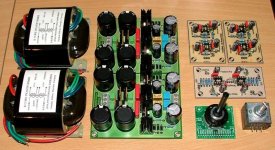
GeWa said:OK, here are the parts so far. Only problem left is to find a deicent housing to put it al in. The power supply is dual so the Freebird and the Yardbirds will have there own separate PS. Maybe a bit over the top but who cares.😀
Cheers
Hey that is looking very good GeWa! 🙂
I really dig those transformers, what type are they? Who makes them?
Enjoy the belgian beer. 😀
Cheers!
Russ
Russ
The label says: Nanhai Dibao Electric Factory.
I got them from HiFituning in germany.
http://www.hifituning.com/html/r-core_trafos.html
Aaah yes,.......Belgian beers
Cheers
The label says: Nanhai Dibao Electric Factory.
I got them from HiFituning in germany.
http://www.hifituning.com/html/r-core_trafos.html
Aaah yes,.......Belgian beers
Cheers
About to get these made.
OK, I think the freebird is well tested, and ready to rock. So Here is how it looks right now. Let me know if you see anything I should change before I get some of these made for sale. 🙂
Cheers! (drinking a well made bridgeport stout)
Russ
OK, I think the freebird is well tested, and ready to rock. So Here is how it looks right now. Let me know if you see anything I should change before I get some of these made for sale. 🙂
Cheers! (drinking a well made bridgeport stout)
Russ
Attachments

Member
Joined 2003
The only problem I found when assembling the Freebird as well as the power supply is that the electolytic capacitors are VERY close together and I had a hard time getting them flush to the board. An extra 0.5mm-1mm clearance is probably all they need.
DcibeL said:The only problem I found when assembling the Freebird as well as the power supply is that the electolytic capacitors are VERY close together
Ah thank you! Exactly the kind of input I was looking for. Are you talking about the PS caps? It is the only board that has electrolytics close to each other.
I didn't have that problem, but some of my caps don't sit flat anyway - I think it was the caps having non-flat bases more than tight spacing. Some small EL Caps seem to have a rubber protusion at the base...
Michael
Michael
Member
Joined 2003
On the Freebird the EL caps sit very close to the 100nF caps where there is plenty of room to space them out a little more. Looking at the Yardbird there seems to be just a tad more room between these caps which is all you would need. On the Power supply, the 220uF caps as well as C3 have this problem. It would seem as though the lip at the base of the capacitor sticks out just slightly past the diameter of the cap. I used 50V 220uF caps which may be slightly larger than the size you designed the board for, so these caps may not be a problem for other people. I am sure the regulators don't give off any amount of heat (I haven't powered the board up yet), but perhaps they could be moved closer to the edge of the board to give them a little more breathing room?
Yes, the caps do have a rubber base, but if you press them to the board as you solder them in place they will be flush and quite solidly in place. Sorry if I am being picky here, but soldering is my job, until I am done school that is.
Yes, the caps do have a rubber base, but if you press them to the board as you solder them in place they will be flush and quite solidly in place. Sorry if I am being picky here, but soldering is my job, until I am done school that is.
Actually you are doing as I asked. Be very picky please. 🙂
I will move things around a bit. 🙂
The regulators on the PS are placed so that a TO220 heatsink can easily be mounted, but no they don't get even close to hot, even with no HS.
I will move things around a bit. 🙂
The regulators on the PS are placed so that a TO220 heatsink can easily be mounted, but no they don't get even close to hot, even with no HS.
- Status
- Not open for further replies.
- Home
- Amplifiers
- Chip Amps
- completed chipamp pre