The value really isn't critical and no harm will come even if you fitted something totally inappropriate.
So for 50k the value would be around 6k (about an 8.3:1 ratio as a rule of thumb) but we already have a 22k present in the form of the resistor from pin 10 of the chip to ground. And to complicate it further a 1k that appears in series with that one... but all of that doesn't really matter... as it is very non critical.
So that means we need around 8k2 as an added resistor. 8k2 and 22k in parallel (we forget the 1k) gives an equivalent of 5973 ohms which looks pretty good to me 🙂
Use what you have if it saves ordering more parts, 10k, 4k7, try them and see.
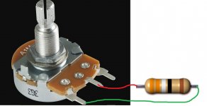
So you solder this resistor on the volume control itself. It goes between the wiper (middle pin) and the ground end of the pot. Do the same on both channels.
And remember... this doesn't make the amp louder at all, it simply alters the ratio of perceived volume vs rotation angle of the control.
So for 50k the value would be around 6k (about an 8.3:1 ratio as a rule of thumb) but we already have a 22k present in the form of the resistor from pin 10 of the chip to ground. And to complicate it further a 1k that appears in series with that one... but all of that doesn't really matter... as it is very non critical.
So that means we need around 8k2 as an added resistor. 8k2 and 22k in parallel (we forget the 1k) gives an equivalent of 5973 ohms which looks pretty good to me 🙂
Use what you have if it saves ordering more parts, 10k, 4k7, try them and see.
So you solder this resistor on the volume control itself. It goes between the wiper (middle pin) and the ground end of the pot. Do the same on both channels.
And remember... this doesn't make the amp louder at all, it simply alters the ratio of perceived volume vs rotation angle of the control.
Attachments

I've done all of that now and it sounds just great- even better (and louder) than before! But just earlier I was beginning to give up hope again. I'd added the two resistors to the pot and swapped the 1k ones for some 470 ohm resistors. On turning on the amp, I didn't get the usual bright bulb, then nothing (but music), instead all I got was a low glow from the bulb. No sound, no buzzing, nothing. I looked over everything again painstakingly and tried to see what I'd done wrong. After leaving it for a bit, I came back and realised that I'd plugged the soldering iron into the DBT and that was what I was testing! I plugged the actual amp cord in (they are identical) and all was well again. Phew 🙂
🙂 things like that are easily done and have you thinking for a moment.
As it is now all working well I think that is probably as far as you can go with this one... unless you really want to keep refining it more and more 😉
There are at least three simple additions to the basic circuit that could be done and they may (or may not) make any noticeable difference to sound quality...
So three things:
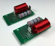
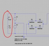
1/ The output feed to the speaker should really include a small air spaced inductor. This is to isolate the chip from any very small parasitic capacitance of the speaker leads and it plays a big part in improving stability into reactive loads. 99% of commercial amps include this part.
(NAIM amplifiers many years ago had a massive problem because they didn't include this component and many users who tried exotic cables were finding their amplifiers were failing catastrophically)
So a small coil wound around a non magnetic former (or simply air spaced) is all that is needed. Typically the wire is enamelled copper wire and would be around 1 to 1.5 mm in diameter. You would wind about 15 turns around the former which can then either be removed or retained if non magnetic (it must be non magnetic if you retain the former).
A 10 ohm 2 watt resistor is then connected across the coil to provide electrical damping.
The coil must go electrically after the Zobel network (that 0.1uF cap and 10 ohm). If that is not done then the Zobel becomes totally ineffective and bad things might happen 😀
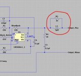
2/ An RF filter can be added to the input to help stop low level high frequency noise from entering the amplifier.
This consists of a small capacitor placed across the 22k that goes to pin 10 which is the + input. 120 or 150pF (PICO, very small) is about as high as we can go given the 50k volume pot you have. The cap should be a small film type rather than a ceramic or mylar.
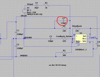
3/ A single snubber can be added to the transformer secondary. This can help noise from the diodes as they come in and out of conduction from entering the power supply. It can be wired across the bridge rectifier AC input.
It also filters noise passing from primary to secondary.
The resistor is not critical but should be a 1 or 2 watt carbon or metal film type. Anything from 1 ohm to 4.7 ohm is OK.
The capacitor is important and must be a good quality film type suitable for the voltage it will see which is going to be around 60 volts peak to peak and even more with transients.
So we need something really good here such as 250 volt rated part.
If you try any of these then I would recommend you revert back to the bulb tester for initial switching on to make sure all is well.
1/ The output feed to the speaker should really include a small air spaced inductor. This is to isolate the chip from any very small parasitic capacitance of the speaker leads and it plays a big part in improving stability into reactive loads. 99% of commercial amps include this part.
(NAIM amplifiers many years ago had a massive problem because they didn't include this component and many users who tried exotic cables were finding their amplifiers were failing catastrophically)
So a small coil wound around a non magnetic former (or simply air spaced) is all that is needed. Typically the wire is enamelled copper wire and would be around 1 to 1.5 mm in diameter. You would wind about 15 turns around the former which can then either be removed or retained if non magnetic (it must be non magnetic if you retain the former).
A 10 ohm 2 watt resistor is then connected across the coil to provide electrical damping.
The coil must go electrically after the Zobel network (that 0.1uF cap and 10 ohm). If that is not done then the Zobel becomes totally ineffective and bad things might happen 😀
2/ An RF filter can be added to the input to help stop low level high frequency noise from entering the amplifier.
This consists of a small capacitor placed across the 22k that goes to pin 10 which is the + input. 120 or 150pF (PICO, very small) is about as high as we can go given the 50k volume pot you have. The cap should be a small film type rather than a ceramic or mylar.
3/ A single snubber can be added to the transformer secondary. This can help noise from the diodes as they come in and out of conduction from entering the power supply. It can be wired across the bridge rectifier AC input.
It also filters noise passing from primary to secondary.
The resistor is not critical but should be a 1 or 2 watt carbon or metal film type. Anything from 1 ohm to 4.7 ohm is OK.
The capacitor is important and must be a good quality film type suitable for the voltage it will see which is going to be around 60 volts peak to peak and even more with transients.
So we need something really good here such as 250 volt rated part.
If you try any of these then I would recommend you revert back to the bulb tester for initial switching on to make sure all is well.
Attachments
🙂 It's entirely up to you if you think it is worth it. The coil is definitely good practice purely from a reliability point of view though.

🙂 It's entirely up to you if you think it is worth it. The coil is definitely good practice purely from a reliability point of view though.
When you have wound the coil and before attempting to solder the ends you will need to scrape off the enamel at each end or the solder may/will not adhere to it.
Good point. The varnish can be super tough and it resists solder. A bit of sandpaper or a fine file is needed.
I don't seem to be able to find a 150pF 🙁. I usually use RS components who normally have everything I need.
Hmm... expensive as in quantities of ten. This is the preferred type though.
RS PRO Polystyrene Capacitor 150pF 160V dc +-2.5% Tolerance Through Hole 4mm diameter | RS Components
Also in fives:
RS PRO Polystyrene Capacitor 150pF 63V dc +-1% Tolerance Through Hole 7.5mm diameter | RS Components
RS PRO Polystyrene Capacitor 150pF 160V dc +-2.5% Tolerance Through Hole 4mm diameter | RS Components
Also in fives:
RS PRO Polystyrene Capacitor 150pF 63V dc +-1% Tolerance Through Hole 7.5mm diameter | RS Components
- Home
- Amplifiers
- Chip Amps
- Complete novice alert! *don't read if easily annoyed by stupid questions*