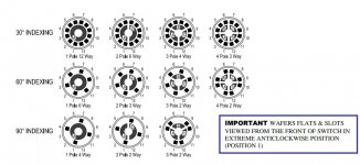
All you need is a simple switch such as a 3 pole 4 way. You would use 2 of the poles and either leave the 3rd unused or you could have it control LED's to show which input was selected.
4 way means it turns through four positions but (so up to four inputs if want) but these have an adjustable end stop so you can make it only click in two positions.
The common pin of each section is the output (so left for one channel and right for the other channel) and the two inputs wire to the other outer pins.
If you have one in front of you it all makes sense 🙂
https://cpc.farnell.com/lorlin/ck1026/switch-3pole-4-pos/dp/SW04138
Attachments

That’s great! Something that seems not too complicated! �� I’ll order one right now. Thank you.
Put your meter on ohms and measure, it will make sense then.
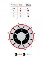
Turn the switch fully one way and then put one of your your meter leads on A. You will get a reading (continuity) between A and either 1 or 4. Either because it depends which way around we are looking at it. If it is between A and 4 then turn the switch to the other end... so what is below makes sense.
Lets say continuity was between A and 1.
You will then then find that B and 5 also have continuity and also C and 9.
There is NO continuity between any of the three groups, A,B and C under any condition. They all behave as individual four way switches.
So... continuity between A and 1, B and 5 and C and 9
Now click the switch one position and remeasure. You will find A and 2, B and 6 C and 10 now have continuity.
Click another position around and now its A and 3, B and 7 and so on.
Yes, it comes out exactly as you've said 🙂 So with my original wiring (to the potentiometer from the one input), there are 4 wires (left, right and two grounds). How do I now connect these to the switch?
The grounds do not connect to the switch. They stay as they are. If you add another input (or inputs) you run the grounds from the the new sockets to the same place as the existing pair.
You take the left signal wire that currently goes from the left input socket to the pot and connect this to 'A' on the switch. In other words you unsolder it from the socket and move it to 'A'.
You do the same for the right socket this time moving it to 'B'.
You now wire '1' to the left input socket.
Now wire '5' to the right socket.
That completes the wiring for one input.
The second input simply add a wire from the new left input socket to '2' and the new right input socket to '6'.
If you wanted a third or fourth input you would use 3 and 4 for the left sockets and 7 and 8 for the right.
When you have wired it up check that you have continuity from the centre pin of the appropriate input socket to the pot. As you click the switch round you should then loose that connectivity and find now that the second set of inputs connects.
The Lorlin type switches I mentioned have adjustable end stops so you can make it so it only clicks in two positions if you want.
So can the new grounds join onto the existing grounds? I mean, can I join grounds from input 2 and 3 onto input 1? Or do they have to go to the pot (where they go to at the moment) then on to the point next to the big cap?
Well that's good 😉 and you can use the unused section of the switch to light an LED for each input if you wish.
You need one LED for each input and there are a couple of ways of doing this...
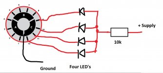
You take a single resistor and connect it to the positive supply. The value of the resistor is chosen to set the LED current (brightness). Lets say the positive supply is 20 volts. A typical starting point for modern high brightness LED's could be as low as 2 milliamp.
So R=V/I which 20/ 0.002 giving 10k. A 0.5 watt is perfect.
(before anyone says I haven't accounted for the LED volt drop I'll just say that it doesn't matter given a high-ish supply voltage such as 20 volts)
You connect the anode of all the LED's together and connect these to the other end of the 10k.
Each cathode lead of the LED now goes in turn to pins 9, 10, 11 and 12 on the switch.
Pin 'C' of the switch connects to ground. So the switch connects a different LED across the supply as you rotate it. Alter the 10k to alter the brightness, a higher R equals dimmer.
And that's it 🙂
Attachments
Thanks for that. I have a slightly different question now. I have a JVC turntable that doesn't have a pre-amp. Is this something I could make? Is it worth it or should I just buy one?
A ready made one is easiest, building your own needs much care. It is not that it is complicated, it is just that the gain of a phono stage is so high that it can be prone to picking up hum and noise. It all requires care.
Something like this:
Hi-Fi RIAA Phono Preamp
It would have to be built on the PCB for the project, in fact any design would need a PCB, you can not do point to point on stripboard for this, the results would be poor.
Something like this:
Hi-Fi RIAA Phono Preamp
It would have to be built on the PCB for the project, in fact any design would need a PCB, you can not do point to point on stripboard for this, the results would be poor.
I'm also getting a loud 'pop' when I turn the amp on. I don't seem to remember this happening when I use the DBT. Also, after listening to it for a while now, it's lacking a bit of bass. Can I improve this easily?
Last edited:
Switch on and off noises are common on many amps and occur because the DC voltage at the output needs a fraction of a second to settle to zero. The bulb will have the effect of slowing the rise time of the rails, in other words they build up (relatively) slowly.
A relay delay on the speaker output is usually used and is a 100% fix for this.
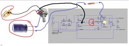
Have you got the 100uF cap fitted to pin 8 of the LM3886 ? That is supposed to mute the output for a short period to prevent noises. Note the polarity of the cap. I can't remember what value resistor you used to pin 8 but it needs to be appropriate for the supply and cap value for the mute to work.
It shouldn't lack bass at all because the amp output is DC coupled. The input coupling capacitor and the feedback return cap could reduce bass if they were to small.
You will have to check these two cap values. If they are as here then it won't be lacking bass.
Also make sure your speakers are phased correctly. If you have the wiring to the speaker sockets reversed on just one channel then bass will audibly cancel out. One speaker pushes as the other pulls. That cancels the bass. Just swap the wires to one speaker over to prove that.
A relay delay on the speaker output is usually used and is a 100% fix for this.
Have you got the 100uF cap fitted to pin 8 of the LM3886 ? That is supposed to mute the output for a short period to prevent noises. Note the polarity of the cap. I can't remember what value resistor you used to pin 8 but it needs to be appropriate for the supply and cap value for the mute to work.
It shouldn't lack bass at all because the amp output is DC coupled. The input coupling capacitor and the feedback return cap could reduce bass if they were to small.
You will have to check these two cap values. If they are as here then it won't be lacking bass.
Also make sure your speakers are phased correctly. If you have the wiring to the speaker sockets reversed on just one channel then bass will audibly cancel out. One speaker pushes as the other pulls. That cancels the bass. Just swap the wires to one speaker over to prove that.
Attachments
There is no capacitor on the 8 pin, just a 10kΩ resistor. I want to re-phrase what I said: it doesn't really lack bass, it's just that I'd like more 🙂
Last edited:
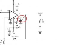
So we need to add the capacitor as it is shown on the diagram above.
Note that + on the cap goes to ground. I'm not sure what voltage the cap will see in operation but we can say it will only see voltages that are negative on that pin and so that means it needs to be rated to at least the value of one of the rails i.e. for a -/+28 volt supply the cap can only see 28 volts at most and so a 35v or higher cap would be used.
If you can solder neatly then a small cap can be fitted directly between pin 8 and pin 7 which is ground.
To get more bass means you need an active bass boost circuit which is really half way to a proper tone control. As with the phono stage, there are lots of boards and kits available for that although they all seem to include a volume control as well.
One of many:
NE5532 OP-AMP HIFI Amplifier Preamplifier Volume Tone EQ Control Board DIY | eBay
- Home
- Amplifiers
- Chip Amps
- Complete novice alert! *don't read if easily annoyed by stupid questions*