Yes, the chip is the insulated version. Caps have been discharged and I've connected the wires as you've described. There is no real ground yet, is that right?
Ground (which is really an arbitrary point) will be the end of that short wire stub. It is an arbitrary point defined as ground by us.
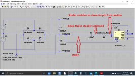
5/ So the next step is now to connect the main feedback resistor which goes between pin 3 and pin 9. We should use 22k here but before you fit it, measure it and be sure it is what you think it is. Neatly form the leads and solder to the pins.
6/ Remember I said it wouldn't be pretty to begin with 🙂
Connect a 1k resistor to pin 9. Solder the resistor as close as is reasonable to the pin, in other words try not to leave the lead to long in length that goes to pin 9. As before, measure the 1k first to make sure it is what it is supposed to be.
7/ What you do now is connect a 100uF cap (or 47uF) neatly to the other end of that resistor and then wire it to the stub. Negative end of the cap goes to the stub via a wire.
So it should look like this:
Attachments
8/ Next up then is to terminate the + input which is pin 10. Connect a 22k resistor to pin 10 (as close to the chip as practicable) and connect the other end of the resistor to the end of the short ground stub. As with all the other steps, measure the resistor first.
9/ Now we connect the 'Mute' pin which is pin 8 to a 10k resistor. The other end of the resistor goes to the negative supply rail on the large power supply caps where you have MINUS 27 volts. This resistor does not need be close to the chip. Again, measure the resistor first.
It should all look like this.
Attachments

Excellent. Well we are nearly ready for a first test but before we do we need to add a little decoupling to the chip.
Do you have any small value caps (say 10uF or 47uF) and if so what voltage rating are they?
Do you have any small value caps (say 10uF or 47uF) and if so what voltage rating are they?
Hmm... what we really need you see is a small cap adding across the supply pins of the chip (so between pins 1/5 and pin 4) and so we need at least 63 volt rating for that.
Do you have any much smaller values that are not electrolytic such as 0.1uF film types such as you might have used in the Zobel network at the output?
The cap is to help ensure stability and even very small values can be effective.
Do you have any much smaller values that are not electrolytic such as 0.1uF film types such as you might have used in the Zobel network at the output?
The cap is to help ensure stability and even very small values can be effective.
I'll post the next bit up while we think what to do on the decoupling.
10/ Now we add the Zobel network. This is the series connected 0.1uF cap and 10 ohm resistor that goes to the output of the chip which is pin 3 and ground.
Connect them in whatever order is easiest. As long as they are in series then it does not matter whether it is the cap or the resistor that is the part that connects to pin 3 of the chip.
Now connect the other end of the series cap/resistor to the OTHER end of that short wire stub. This is important. Look at the diagram. You connect it to the part of the wire nearer to the big caps.
We do it that way because the wire has a small resistance and we do not want to introduce any possibility of feedback into the 'clean' ground at the right hand end of that wire.
I'll look in later 🙂
Attachments
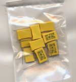
I've got one of these: ECWFE 100nF 450V c.c. ±5% and some of these:
Sorry, I can't make out what they are and don't even remember ordering them 🙁 It says NPX 104K 310VX2M2F
We will try them. 104 is 100000 pico farads which is the same as a 0.1uF or 100nF (nano farad).
So then:
11/ Connect one of these caps between pin 1 and pin 4
That puts the cap across the supply pins of the chip.
Ah... yes it might matter... a lot 🙂
20 watt is massive and they would be very very large physically. Are you sure they are 20 watt?
What did you use on the previous builds that didn't work? Was it those ceramic types?
The 10 ohm should be a non inductive type (so not a wirewound resistor). It is quite a critical part in that respect. A 2 watt carbon or metal film is usually perfect for these.
I never used the ceramic resistors anyway. I've ordered some ordinary 10 ohm ones, should be here in a day or so.
OK.
We are almost at the point of being able to test it but it does need that network for more guaranteed stability.
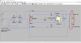
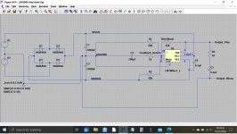
It would be worth you looking it all over at this point. It should look like this and hopefully when we power it up the output voltage of the chip should be very close to zero volts as here.
I didn't know you were ordering parts 🙂 because it would have been good to have some small higher voltage electrolytic caps as well such as 100uF at 63 volt. We would have used those for decoupling rather than just the 0.1uF shown on the diagram.
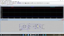
Finally we add the input circuitry (shown at the top) and hopefully it will work. Last image shows the small applied input voltage and the larger amplified output.
We are almost at the point of being able to test it but it does need that network for more guaranteed stability.
It would be worth you looking it all over at this point. It should look like this and hopefully when we power it up the output voltage of the chip should be very close to zero volts as here.
I didn't know you were ordering parts 🙂 because it would have been good to have some small higher voltage electrolytic caps as well such as 100uF at 63 volt. We would have used those for decoupling rather than just the 0.1uF shown on the diagram.
Finally we add the input circuitry (shown at the top) and hopefully
it will work. Last image shows the small applied input voltage and the larger amplified output.Attachments

Yes, I had to get the order in last night before 7pm here as it takes a couple of days 🙁. I'll let you know when I've got them.
So where are we up to?
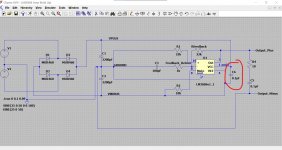
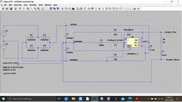
With the 0.1uF and 10 ohm Zobel network in place (as per post #131) and with a 0.1uF across the supply pins 1 and 4 of the chip then I think we are pretty much ready for a basic test.
Make sure it all agrees electrically with this diagram first. At this stage you do not need connect any input or output sockets.
So... we carefully power it up using the bulb tester. The bulb should go out and the chip should remain virtually cold.
Be extremely careful measuring voltages, one slip with the probe could damage the chip. All voltages are measured from that short ground wire.
We measure just three things to see where it is all at.
1/ The DC voltage on pin 3 (and be careful measuring). It should be close to zero.
2/ The DC voltage on pins 1/5 which is the positive rail and should be your +27 volts.
3/ The DC voltage on pin 4 which is the negative supply rail and this should be negative 27 volts.
If we can get to that point we're doing well.
Attachments
- Home
- Amplifiers
- Chip Amps
- Complete novice alert! *don't read if easily annoyed by stupid questions*