The diagram in post #91 was OK apart from the front/back anomaly that aparatusonitus spotted.
Diagram in post #97 is totally wrong. You have the resistors in series and incorrectly connected.
Diagram in post #97 is totally wrong. You have the resistors in series and incorrectly connected.
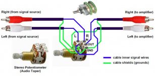
This is how I originally had it and this is what I copied from the person who posted the instructable I am following (https://www.instructables.com/Make-your-first-Serious-Amplifier/)
Attachments

You are tying yourself in knots with this. What you have just posted looks wrong as you appear to have pin 10 going to ground via a 1k
Listen 🙂
Forget the inputs for now. Just connect pin 10 to ground via the 22k and see if the amp powers up correctly and silently. Use the DBT.
Listen 🙂
Forget the inputs for now. Just connect pin 10 to ground via the 22k and see if the amp powers up correctly and silently. Use the DBT.
Okay. Done as instructed 🙂 Now if I disconnect the speaker, the bulb doesn't go out, but it dims.
So now you now need to measure the DC voltage across the speaker output terminals with the speaker still disconnected. You should see almost zero volts.
With nothing connected to the speaker terminal I get 0.01v and with the terminal connected (but no speaker attached) I get -3.0v (?)
The terminals have to be connected internally within the amp... so that is where you measure -3 volts DC I assume. In other words that is the voltage between ground and pin 3 which is the output pin.
If so (and all that follows on based on this scenario) then there is a problem because that voltage should be zero. This will also be why the bulb lights when the speaker is connected. 3
3 volts across a 4 to 6 ohm voice coil would draw anything up to 0.75 amp and that will light the bulb.
So you still have a problem. It is also possible the amplifier could be oscillating (unstable) rather than a pure DC fault.
I really don't know what to suggest to you. The LM3886 is a proven design used by many manufacturers and diy'ers without major issues.
All I could say now is for you to check the voltages on the two input pins.
Pin 10 should be close to zero.
Pin 9 can't be zero if you have -3 volts on the output pin but what do you actually see here.
I suspected as much.
The circuit isn't behaving under fault conditions in such a way that the theory says and so that leads on to suspecting that the amplifier is unstable and oscillating.
A voltage difference between the two input pins of even a millivolt or two should be sending the output hard against one of the rails... that's fact... and yet that isn't happening here and so the only logical conclusion based on raw results is instability.
That means its oscillating at very high frequency which an oscilloscope would show.
If you really want to persevere with this then I would be willing to describe one step at a time how to wire one channel up. It won't be pretty but once it is done you could then tidy it all up.
I'd be very grateful if you could tell me how to go forward. I really don't want to give up on this, but I will if it becomes a complete chore. If it makes it easier for you, you could email me the instructions whenever you get the time? Thanks so much again for your help. Are email addresses allowed on here?
It is best done via the forum really because then it helps others who might be also having problems.
You start with the power supply complete with bulb tester and we first make sure that is working OK and configured correctly.
I know this is all going back to very beginning but its the only way to do it.
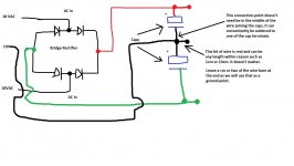
So I need you to end up with the bridge rectifier and two big reservoir caps connected exactly like this. The AC from the transformer comes in the left and you have the split rail DC output voltages at the right.
When powered on the bulb should flick brightly for an instant and then go out.
This is the boring bit 😉 but we have to build it up in stages.
When you have tested it and made sure the DC voltages are OK on the caps (which will be around + and - 25 volts if the transformer is an 18 volt type) then switch off and discharge the caps with a resistor. It will take quite a few seconds with a 10k for example.
You start with the power supply complete with bulb tester and we first make sure that is working OK and configured correctly.
I know this is all going back to very beginning but its the only way to do it.
So I need you to end up with the bridge rectifier and two big reservoir caps connected exactly like this. The AC from the transformer comes in the left and you have the split rail DC output voltages at the right.
When powered on the bulb should flick brightly for an instant and then go out.
This is the boring bit 😉 but we have to build it up in stages.
When you have tested it and made sure the DC voltages are OK on the caps (which will be around + and - 25 volts if the transformer is an 18 volt type) then switch off and discharge the caps with a resistor. It will take quite a few seconds with a 10k for example.
Attachments
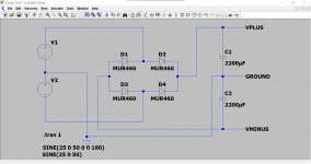
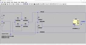
It is going to be easier for me to draw this using a dedicated program. This shows the configuration and also the actual voltages you should see.
V1 and V2 at the left represent the transformer windings.
The DC voltages can be seen on the graph and this is just how an oscilloscope would display it. There is plus 25 at the top and negative 25 at the bottom.
This is a working simulation and so we will build your amp up and prove it works 🙂
V1 and V2 at the left represent the transformer windings.
The DC voltages can be seen on the graph and this is just how an oscilloscope would display it. There is plus 25 at the top and negative 25 at the bottom.
This is a working simulation and so we will build your amp up and prove it works 🙂
Attachments

Great 🙂
First make sure you have one good LM3886 mounted on the heatsink. I'm assuming these are the all plastic insulated packaged devices and not the ones with a bare metal tab.
So now we work around the chip one pin at a time but before we go any further make sure that the big power supply caps are discharged. If not then they can dump all their energy into the chip as you wire it up and that can damage it. From this point on you do not power the circuit again.
Mark all these off as you complete them and check check and double check you have it correct.
1/ Using a very short piece of wire you first link pin 1 to 5 on the chip.
2/ Now take a suitable piece of wire and connect pin 5 to the positive rail on the big power supply caps, the point where you measured plus 27 volts.
3/ Using a similar wire now connect pin 4 to the power supply cap where you measured minus 27 volts.
4/ And again, another wire this time connecting pin 7 to the end of that short wire stub I outlined in the earlier diagram that taps off from the centre point between the two caps.
Lets get it to that point.
- Home
- Amplifiers
- Chip Amps
- Complete novice alert! *don't read if easily annoyed by stupid questions*