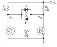
Seems that the leds would only light if there were a rather large mismatch since the voltage mismatch has to be 1.6-1.7 before they light. A variation of 9-10 mA would be necessary across 180 ohms. Probably a ballpark tester for output transistors at best. The one with the anode of the led attached to it's collector would be the low gain one of the pair.
Last edited:
Which Vs did you try? R1 and R2 look like LED pull-down values from +6V.
The suggested Vs was 10v but I tried 5 and 12. Neither did anything.
A test jig to do small signal transistors. Scale would be 1uA per 1mV. Having a pair of transistors that are with in 10mV on all 3 settings would be a fairly good match. R4/R5 and R6/R7 should be closely matched to each other. Intended power supply is a 9 volt battery.
Attachments
I thought about putting an instrumentation opamp in place of the LEDs. With enough gain I could measure small differences.
What do you think about that idea?
What do you think about that idea?
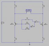
Another question: I don't see how any current is going to flow in both bases in any case but I measured 2.5 volts across the 30k base resistor. What is causing current to flow between the two bases?
Look at Q1 base and notice that Q1 is a PNP transistor. And to open PNP transistor we need a closed path for the Q1 base current from base to ground. As you can see Q1 emitter is tied to Vs via R1. So the only path from Q1 base to ground is via R3 and Q2 base-emitter junction.
And also for NPN transistor to open we need a closed path from Vs. So eventually the current will flow in this circuit:
Vs ---> R1 ---> Q1 base-emitter junction ---> R4 ---> Q2 base-emitter ---> GND. And this current will turn ON both transistors.
And also for NPN transistor to open we need a closed path from Vs. So eventually the current will flow in this circuit:
Vs ---> R1 ---> Q1 base-emitter junction ---> R4 ---> Q2 base-emitter ---> GND. And this current will turn ON both transistors.
RNMarsh had posted this on some thread.
Gajanan Phadte
Ok, so I assembled this circuit but I didn't use the exact resistor values and I didn't have a 25-0-25 microammeter.
I put a 110 ohm resistor in place of the microammeter and measured the voltage across it.
I kept the same PNP transistor and used two different NPN transistors.
Both measured about the same. I guess I will have to use the exact resistor values and buy the analog ammeter.
Any ideas?
A test jig to do small signal transistors. Scale would be 1uA per 1mV. Having a pair of transistors that are with in 10mV on all 3 settings would be a fairly good match. R4/R5 and R6/R7 should be closely matched to each other. Intended power supply is a 9 volt battery.
Ok, I think I have this one figured out.
With two nearly exact transistors, the differential is about .12 volts but it drifts up and down. It takes a while to settle down.
It may help to arrange the transistors so the flat sides touch and put a small piece of tape on to hold them together. The addition of a 1n4148 diode in the base circuit may also reduce variation.
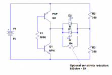
Here is a circuit that will perform like the original one is supposed to, but better:
Without R4, one of the LEDs will practically always be lit (unless the beta's happen to match with extreme accuracy), and the brightness will indicate the degree of mismatch.
If this behavior is not desired, R4 can be added to introduce a threshold: if the mismatch is below a certain value, none of the LEDs will light.
The LEDs could be replaced by a milliameter (and the resistor values adapted)
Attachments
This last looks good.
It seems to me that one could change the V1 supply voltage to vary the currents passing through the DUTs and see if the "matching" is good, or bad, over a range of currents.
It seems to me that one could change the V1 supply voltage to vary the currents passing through the DUTs and see if the "matching" is good, or bad, over a range of currents.
That could be an option, but varying R1 is probably simpler.It seems to me that one could change the V1 supply voltage to vary the currents passing through the DUTs and see if the "matching" is good, or bad, over a range of currents.
In this case, note that if R1 becomes too low combined with high Hfe transistors, there could be a risk of exceeding the Pmax of the transistors tested. Including limiting resistors in the collectors would be a wise precaution.
I'm wondering, there are a lot of $20 or so DMM's that have a little socket to measure HFE/current gain of both PNPs and NPNs. Why not measure a bunch of each, sort each polarity by HFE, then it's easy pick the two that match best?
What's likely happening is your fingers heat up the transistor, increasing its gain (and some other parameters) slightly. Things change until it settles back to room temperature. Perhaps using tweezers to manipulate transistors will reduce this.Ok, I think I have this one figured out.
With two nearly exact transistors, the differential is about .12 volts but it drifts up and down. It takes a while to settle down.
I have one of those plus four other transistor testers. In any case, I just opened the latest Elektor magazine and on page 56 is .... wait for it ... a transistor tester!
Something like 27 ohm each will protect small transistors without interfering with a normal measurement.What value would you choose forn the collector resistors?
They don't need to be matched (nor do the ones anyway).
- Status
- Not open for further replies.
- Home
- Amplifiers
- Solid State
- Complementary transistor matcher?