The usual DMM hFE function is OK for rough batching.I'm wondering, there are a lot of $20 or so DMM's that have a little socket to measure HFE/current gain of both PNPs and NPNs. Why not measure a bunch of each, sort each polarity by HFE, then it's easy pick the two that match best?............
But it does not give the Ib, nor Ic of the test.
It does not control the Tj during the test, there is no control on the power dissipated in the device.
It does not give Vbe.
hFE and Vbe are very dependent on Tj and vary with Ic
For decent matching you need to monitor Ib and Ic and develop a method that somehow controls Tj, or at the least gives a consistent Tj between the DUTs during each test.
On a side note, I am currently testing MPSA18 transistors. I am amazed at the wide disparity in Hfe!
So far they are varying between 600 and 1200! There are about 55 different values represented with 765 the most.
So far they are varying between 600 and 1200! There are about 55 different values represented with 765 the most.
You are very lucky to get such high values of hFE.
Check a couple of samples at 1mA Ic, using a 100r collector resistor and a 10k base stopper.
You can measure hFE and Vbe during the test. See how they compare to the DMM results.
Try to arrange for a Vce to match what is stated in the datasheet.
Check a couple of samples at 1mA Ic, using a 100r collector resistor and a 10k base stopper.
You can measure hFE and Vbe during the test. See how they compare to the DMM results.
Try to arrange for a Vce to match what is stated in the datasheet.
Ok, so I took two of the BC550C with nearly identical Vbe according to the DCA75 PN junction test which takes 34 measurements at different currents and tested them with Fritz' jig:
https://home.comcast.net/~ijfritz/MiscProj/transmat001.pdf
At first I thought there was a problem and then I realized that my meter was reading 0.0003**, almost an order of magnitude less than the 0.002 volts which is considered to be a match.
So it validates the average Vbe measured by the DCA75. I'll post a spreadsheet showing what the graph looks like and also the spreadsheet exported out of the DCA75 software.
As promised, here are some pics:
Attachments
-
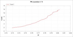 Single PN junction graph of BC550C.jpg157.2 KB · Views: 836
 -
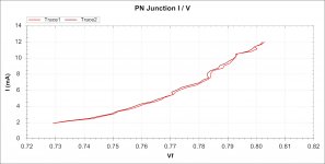 Two PN junction graph of BC550C.jpg166.8 KB · Views: 733
 -
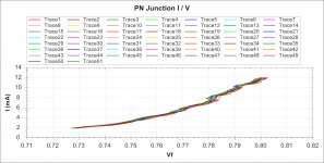 Fifty One PN junction graphs of BC550C.jpg263.1 KB · Views: 729
 -
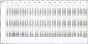 Initial import of Fifty One PN junction graphs of BC550C.jpg187.9 KB · Views: 731
 -
 After Sorting and Matching Vbe of Fifty One BC550C.jpg267.5 KB · Views: 711
The Fritz jig is not much good.
It puts emitter resistors into the test circuit.
That use of Re swamps differences in the DUTs.
The current measuring resistor need to go into the collector leads.
The Re is very effective feedback. You must remove it, or at the very least minimise it.
It puts emitter resistors into the test circuit.
That use of Re swamps differences in the DUTs.
The current measuring resistor need to go into the collector leads.
The Re is very effective feedback. You must remove it, or at the very least minimise it.
Good to know. In any case, after more testing, the measurement settled out at 0.0002 volts but when I swapped the transistors it measured 0.0006.
I don't understand this because the 100k resistors are 0.01% Caddock with a TC of 5.
On that same meter one resistor measures exactly 100,000 and the other measures 100,001 ohms using a 4 wire setup.
I'll go ahead and try the jig in message #14 to see what happens.
I don't understand this because the 100k resistors are 0.01% Caddock with a TC of 5.
On that same meter one resistor measures exactly 100,000 and the other measures 100,001 ohms using a 4 wire setup.
I'll go ahead and try the jig in message #14 to see what happens.
The post14 is a Wheatstone bridge.
It can be made very sensitive to small changes.
The jig is comparing half supply voltage (junction of the two resistors) to the output offset voltage at the junction of the two transistor collectors.
A small change in output offset ref. the 1/2Vsupply, is a measure of "unmatch" in the two DUTs.
If the DUTs match at one Ic, but move out of match as the Ic is changed, then the two transistors do not track each other over the range of tested Ic.
That is a well-known circuit. But unfortunately, not so good for matching complimentary power BJts.Here is a circuit that will perform like the original one is supposed to, but better:
The LEDs could be replaced by a milliameter (and the resistor values adapted)
Do you mean for my circuit, with a milliammeter? In this case, its depends on the range of the instrument, and the sensitivity to deviations you want to achieveIf I replaced the LEDs, what values should I use for the resistors?
What type of circuitry depends on Hfe matching of complementary devices ? Looking for usefully enhanced performance here.
#9
You can substitute a DVM for the panel meter. various R values are used to select closest to the intended circuits operating current. here is the picture of the original unit and I still use it from time to time. This was built about 35 years ago as part of an article I published. It is especially useful for matching complimentary push-pull topologies. I used it on the first Current-Mode Amp -CFA- topology that was all direct (DC) coupled.

THx-RNMarsh
RNMarsh had posted this on some thread.
Gajanan Phadte
You can substitute a DVM for the panel meter. various R values are used to select closest to the intended circuits operating current. here is the picture of the original unit and I still use it from time to time. This was built about 35 years ago as part of an article I published. It is especially useful for matching complimentary push-pull topologies. I used it on the first Current-Mode Amp -CFA- topology that was all direct (DC) coupled.
THx-RNMarsh
Last edited:
This is an interesting and useful topic!
However, what I could also need, is a way to match types of PNP and NPN-tansistors, so that two amp-channels are as closely matached as possible. How can I accomplish that?
However, what I could also need, is a way to match types of PNP and NPN-tansistors, so that two amp-channels are as closely matached as possible. How can I accomplish that?
I know, I guess you miss understand me. My bad. Let me explain.This thread is all that you want. Complementary means NPN and PNP.
Gajanan Phadte
I mean in matching two NPN's of the same type, each used in the same place in individual amp channels. Same for PNP's.
Aside from that, I'm beginning to understand that matching transistors is a difficult matter, since matching can be done on several parameters, all depending on the intended use and operating range of the transistor.
So, assuming you buy a number of transistors (both small signal and output devices), all from the same batch, is it really necessary to match all like transistors to get a well performing amplifier? Or is matching only necessary to squeeze every last bit of juice out of it?
Last edited:
the VAS of a "normal" Power Amplifier passes current to and from the next stage, either complementary Drivers or complementary Pre-Drivers.What type of circuitry depends on Hfe matching of complementary devices ? Looking for usefully enhanced performance here.
These two devices draw current from the VAS line and re-inject it back into the VAS line.
If the currents vary from each other, then the VAS line is being disturbed and the amplifier distorts.
If the drivers have other parameters that vary the load on the VAS, then these too will affect the way the VAS line responds to signals. Equals more distortion.
That leaves a lot for the NFB to try to attenuate.
Channel to channel matching is much less important.I know, I guess you miss understand me. My bad. Let me explain.
I mean in matching two NPN's of the same type, each used in the same place in individual amp channels. Same for PNP's.
Aside from that, I'm beginning to understand that matching transistors is a difficult matter, since matching can be done on several parameters, all depending on the intended use and operating range of the transistor.
So, assuming you buy a number of transistors (both small signal and output devices), all from the same batch, is it really necessary to match all like transistors to get a well performing amplifier? Or is matching only necessary to squeeze every last bit of juice out of it?
A good design removes much of the semiconductor variability from the final performance. A good design will work if the correct "type" is used in the correct location. Small changes in semiconductor parameters should not affect performance.
- Status
- Not open for further replies.
- Home
- Amplifiers
- Solid State
- Complementary transistor matcher?